Hello Users
Our qualexe service will not be available in between 11:30 pm to 4:00 am due to server maintenance activity
Previous Years Papers

| Subject | Number of questions |
|---|---|
| POWER ELECTRONICS & DRIVES | 14 |
| CONTROL SYSTEM ENGINEERING | 27 |
| ELECTRICAL MACHINES | 22 |
| POWER SYSTEM | 53 |
| SIGNALS & SYSTEMS | 16 |
| DIGITAL ELECTRONICS | 18 |
| MICROPROCESSOR AND MICROCONTROLLER INTERFACING | 4 |
| ELECTRICAL WIRING | 3 |
| UTILIZATION OF ELECTRICAL ENERGY | 5 |
| ELECTROMAGNETICS | 13 |
| ELECTRICAL ENERGY CONSERVATION AND AUDITING | 1 |
| ELECTRICAL CIRCUIT ANALYSIS | 20 |
| BASIC ELECTRONICS | 2 |
| MEASUREMENT & INSTRUMENTATION | 2 |
| Total | 200 |
Correct Ans: D
Solution:
\(\Rightarrow\) Power MOSFETs indeed have bidirectional current capability mainly because of the presence of the anti-parallel body diode inside them.
Correct Ans: C
Solution:
\(\Rightarrow\) Schottky power diode \(\rightarrow\) Majority carrier device (conduction mainly due to electrons, no significant minority carrier storage).
\(\Rightarrow\) Power MOSFET \(\rightarrow\) Majority carrier device (electrons in n-channel or holes in p-channel dominate).
\(\Rightarrow\) Gate Turn-OFF thyristor (GTO) \(\rightarrow\) Minority carrier device (both electrons and holes participate in conduction — bipolar conduction)
Correct Ans: B
Solution:
\(\Rightarrow\) Silicon controlled rectifier is a semi controlled device as it can be turned on by gate pulse, but cannot be turned off by removing the gate pulse.
Correct Ans: A
Solution:
\(\Rightarrow\) The minimum firing anlge required for single phase half bridge rectifier with E load is given by :
\(\quad \quad \alpha = \sin^{-1} \frac{E}{V_m} = \sin^{-1} \frac{100}{\sqrt 2 \times110 } \approx 40^{\circ} \).
\(\Rightarrow\) Hence Statement 1 is correct.
\(\Rightarrow\) The converter will conduct for for \(40^{\circ}\) to \(140^{\circ} (180^{\circ} - 40^{\circ})\)
\(\Rightarrow\) For firing angle \(60^{\circ}\), the converter will conduct for \(60^{\circ}\) to \(140^{\circ}\).
\(\Rightarrow\) The current will raise from zero at \(60^{\circ}\), will be maximum at \(90^{\circ}\) and start falling after it.
\(\Rightarrow\) Hence, statement 2 is also correct.
Correct Ans: A
Solution:
\(\Rightarrow\) Commutation in power electronics refers to turning off a conducting switch by transferring its load current to another path (another switch or a commutation network).
Correct Ans: B
Solution:
\(\Rightarrow\) Duty cycle: \(D = V_{\text{out}}/V_{\text{in}} = 20/50 = 0.4\).
\(\Rightarrow\) On-time: \(t_{\text{on}} = DT_s = 0.4\times50,\mu\text{s} = 20,\mu s\).
\(\Rightarrow\) Off-time: \(t_{\text{off}} = (1-D)T_s = 0.6\times50,\mu\text{s} = 30,\mu s\).
\(\Rightarrow\) Now, \(\:\:\Delta i_L = \dfrac{(V_{\text{in}} - V_{\text{out}})}{L}DT_s\)
\(\Rightarrow\) \(\:\: \Delta i_L = \frac{30\text{V}}{400\times10^{-6} \text{H}}\times20\times10^{-6} \text{s} = 1.5\text{ A}\)
\(\Rightarrow\) In steady state for a buck in continuous mode, the average inductor current \(I_{L,\text{avg}}\) equals the load current, so \(I_{L,\text{avg}} = I_{\text{load}} = 1A.\) With a triangular ripple of \(1.5, A\) p–p, the peak and valley inductor currents are:
\(\rightarrow\)
\(I_{L\max} = I_{L,\text{avg}} + \frac{\Delta i_L}{2} = 1 + 0.75 = 1.75 A\)
\(\rightarrow\) \(I_{L\min} = I_{L,\text{avg}} - \frac{\Delta i_L}{2} = 1 - 0.75 = 0.25 A.\)
\(\Rightarrow\) Since \(I_{L,\min} = 0.25 A\) remains positive (i.e. the inductor current never falls to zero during any cycle), the converter is operating in continuous conduction mode (CCM).
Correct Ans: C
Solution:
\(\Rightarrow\) The output voltage and conversion ratio are affected by the load resistance because the time it takes for the inductor current to reach zero depends on the load.
\(\quad \rightarrow\) Hence statement 1 is false.
\(\Rightarrow\) In DCM, the inductor current starts from zero, rises to a peak value, and then falls back to zero within a switching cycle. Since the current reaches zero, the peak ripple current must be greater than the average inductor current.
\(\quad \rightarrow\) Hence statement 2 is True.
Correct Ans: A
Solution:
The equation of ripple voltage is given by, \(\quad \Delta V_{C(pp)} \;=\; \frac{I_{\mathrm{out}}\;D}{C\,f_s}\;\le\; 0.01V_o\)
where
\(\rightarrow\) \(D = 1 - \frac{V_{\mathrm{in}}}{V_o} = 1 - \frac{12}{30} = 0.6\)
\(\rightarrow\) \(I_{\mathrm{out}} = \frac{V_o}{R} = \frac{30}{50} = 0.6\;\mathrm{A}\)
\(\rightarrow\) \(f_s = 25\;\mathrm{kHz}\),
\(\rightarrow\) \(\Delta V_{C(pp)} \le 0.01\times 30\;\mathrm{V} = 0.3\;\mathrm{V}\)
\(\Rightarrow\) Solving for \(C\):
\(\implies\)\(C \;\ge\; \frac{I_{\mathrm{out}}\;D}{f_s\;\Delta V_{C(pp)}} = \frac{0.6 \times 0.6}{25\,000 \times 0.3}\)
\(\implies\)\(C = 4.8\times 10^{-5}\;\mathrm{F} = 48\;\mu\mathrm{F}.\)
Correct Ans: B
Solution:
\(\Rightarrow\) The low reverse recovery time allows the fast switching of semiconductor device.
Correct Ans: B
Solution:
\(\Rightarrow\) In Unipolar PWM, the dominant harmonic will be seen at : \(2M_f\pm 1 = 2\times 38 \pm 1 = 75, 76\)
(\Rightarrow\) Hence the first dominant harmonic will be \( 75^{th}\).
Correct Ans: A
Solution:
\(\Rightarrow\) A quasi‐square–wave output by voltage‐cancellation in a single‐phase H-bridge is realized by driving one leg with a low-frequency square‐wave and the other with a high-frequency unipolar SPWM (sinusoidal PWM) signal.
\(\Rightarrow\) This “hybrid” scheme causes the rapid SPWM pulses to cancel during alternate half-cycles, leaving a three‐level, quasi-square waveform at the output.
Correct Ans: B
Solution:
Under linear sinusoidal PWM:
\(\Rightarrow v_{ph,\text{peak}} = \frac{m_a\,V_{dc}}{2} = 50 \:V\)
\(\Rightarrow V_{LL,\text{rms}} = \frac{v_{LL,\text{peak}}}{\sqrt{2}}= \frac{50\sqrt{3}}{\sqrt{2}} = 61.2 \;\mathrm{V} \)
Correct Ans: B
Solution:
\(\Rightarrow\) In a 3-phase square wave inverter, the harmonics are generally odd-order harmonics (3rd, 5th, 7th, etc.)
\(\Rightarrow\) Also, triplen harmonics (3rd, 9th, 15th, etc.) are absent in square wave operation.
Correct Ans: D
Solution:
\(\Rightarrow\) For 8051:
\(\textbf{Machine cycle} = 12\: \text{ clock cycles (Statement 1 true)}\).
\(\textbf{Minimum instruction cycles} = \text{1 (e.g., NOP) (Statement 2 true).}\)
Correct Ans: A
Solution:
\(\Rightarrow\) The ampacity (current-carrying capacity) of a wire depends mainly on its cross-sectional area, and Ohm's Law plus Joule's Law :
1. Resistance of a wire:
\[
R = \rho \frac{L}{A}
\]
where:
\( R \) = resistance,
\( \rho \) = resistivity of material,
\( L \) = length,
\( A \) = cross-sectional area.
\(\therefore\) Smaller \( A \) (thinner wire) \(\rightarrow\) Higher \( R \).
2. Power loss (heating) in the wire:
\[
P = I^2 R
\]
where:
\( P \) = heat produced,
\( I \) = current,
\(\therefore\) Higher \( R \) and large \( I \) \(\rightarrow\) more heat generated.
\(\implies\) The smaller wire heats up faster for the same current because of higher resistance, and can burn if the current exceeds its ampacity.
\(\therefore\) The overcurrent device must protect the smaller wire by being rated no more than its safe current limit.
Correct Ans: D
Solution:
\(\Rightarrow\) \(\text{25-ft Tap Rule =}\) No fuse/breaker needed at the supply point if below these 3 conditions are met:
1. Length limit:
\[
\text{Length} \leq 25 \, \text{feet}
\]
(Smaller wire must be 25 ft or less and protected from physical damage.)
2. Ampacity rule:
Ampacity of tap wire \(\geq \frac{1}{3} \times\) current rating of the main breaker or fuse protecting the bigger wire.
3. End protection: Tap wire must end in one overcurrent device rated \(\leq\) tap wire’s ampacity.
Correct Ans: D
Solution:
Statement-1:
\(\Rightarrow\) Building Automation System (BAS) is a type of Distributed Control System (DCS) because it uses multiple controllers distributed across the building to monitor and control systems.
Statement-2:
\(\Rightarrow\) BAS manages important building operations like:
\(\rightarrow\) Fire and flood safety
\(\rightarrow\) Lighting control
\(\rightarrow\) HVAC (Heating, Ventilation, and Air Conditioning)
\(\rightarrow\) Humidity and ventilation systems
\(\therefore\) Statement-2 is also true.
Correct Ans: D
Solution:
Statement-1:
\(\Rightarrow\) Demand Side Management (DSM) is a special form of Demand Response (DR) that mainly focuses on load shifting (moving electricity use from peak to off-peak times) and aims for long-term energy efficiency among consumers.
Statement-2:
DSM architecture is specifically designed to influence the timing of electricity use, helping users optimize when and how much electricity they consume.
\(\therefore\) Both statements are true.
Correct Ans: A
Solution:
\(\rightarrow\) Option A is Incorrect:
\(\Rightarrow\) Smart meters do allow bidirectional power flow.
\(\implies\) Ex. Homes with solar panels — during the day, they can send extra electricity back to the grid.
\(\Rightarrow\) Smart meter measures =
\[
\text{Power In (Grid} \to \text{Home)} \quad \text{and} \quad \text{Power Out (Home} \to \text{Grid)}
\]
\(\therefore\) Saying "no bidirectional flow" is incorrect.
\(\Rightarrow\) Other Options are Correct:
\(\implies\) Accelerating Renewables and EVs:
Smart meters provide detailed, real-time data to manage solar/wind power and EV charging.
\[
\text{Smart Meter} \Rightarrow \text{Better Traffic Control for Modern Grid}
\]
\(\implies\) User Interface Notification:
Unlike old meters, smart meters offer real-time energy usage data via display or app, helping users become energy-saving users.
\(\implies\) Detecting Distributed Generation:
Smart meters can identify homes generating their own power (like solar rooftops), which is crucial for grid management.
\(\implies\) Smart Meters = Two-way Communication + Two-way Power Flow + Smarter & Greener Grid
Correct Ans: A
Solution:
Statement-1:
\(\rightarrow\) Smart Building Energy Automation (SBEA) includes the Battery Management System (BMS) — it does not exclude it.
\(\therefore\) Statement-1 is False.
Statement-2:
\(\rightarrow\) SBEA monitors and controls multiple battery packs by tracking important battery health indicators like: SOC (State of Charge), SOH (State of Health), DOD (Depth of Discharge).
\(\therefore\) Statement-2 is True.
Correct Ans: D
Solution:
\(\Rightarrow\) Room Cavity Ratio (RCR):
\[
\text{RCR} = \frac{L \times W \times H}{(L + W)^2 \times (H + L)}
\]
Where:
\(L\) = Room Length = 120 feet
\(W\) = Room Width = 60 feet
\(H\) = Ceiling Height = 16 feet \(\quad\because\) (The luminaire is suspended 4 feet below the ceiling, and the work plane is 4 feet above the floor.)
\[
\text{RCR} = \frac{120 \times 60 \times 16}{(120 + 60)^2 \times (16 + 4)} = 4
\]
Correct Ans: B
Solution:
\(\Rightarrow\) Color Rendering Index (CRI) measures how well a light source shows colors compared to natural light or a black body radiator (like the sun).
\(\rightarrow\) CRI is expressed in percentages, with \(100 \%\) being the best (perfect color rendering).
Correct Ans: B
Solution:
\(\Rightarrow\) Illuminance (E):
\[
E = \frac{UF \times MF \times \Phi}{A}
\]
Where:
\(UF = 0.6\) (Utilization Factor)
\(MF = 0.9\) (Maintenance Factor)
\(\Phi = 10,000\ \text{lumens}\) (Total luminous flux)
\(A = L \times W = 10 \times 6 = 60\ \text{m}^2\) (Area of the room)
\[
E = \frac{0.6 \times 0.9 \times 10,000}{60} = 100\ \text{Lux}
\]
Correct Ans: B
Solution:
\(\Rightarrow\) Room Index (RI):
\[
\text{RI} = \frac{L \times W}{H^2}
\]
Where:
\(L = 12\ \text{m}\) (Room Length)
\(W = 8\ \text{m}\) (Room Width)
\(H = 4\ \text{m}\) (Mounting Height)
\[
\text{RI} = \frac{12 \times 8}{4^2} = \frac{96}{16} = 1.6
\]
Correct Ans: C
Solution:
\(\Rightarrow\) As per the National Electrical Code (NEC), the maximum resistance for a grounding electrode (such as a single rod, pipe, or plate) to earth should not exceed \(25 \Omega\) to ensure safe grounding and effective fault clearing.
\(\rightarrow\) This is critical to avoid dangerous voltage differences that could harm people or equipment.
Correct Ans: D
Solution:
Phase lead controller max phase: \(\phi_{\text{max}} = \sin^{-1}\left(\frac{1 - \alpha}{1 + \alpha}\right)\), where \(\alpha = \frac{1}{3}\). Thus, \(\phi_{\text{max}} = 30^\circ\).
Correct Ans: C
Solution:
\(\Rightarrow \textbf{State space models}\) are \(\textbf{not unique}\) (Statement 1 false) but can be derived from transfer functions (Statement 2 true).
Correct Ans: B
Solution:
\(\Rightarrow\) Characteristic equation: Denominator of closed-loop TF = \((s + 1)^2(s + 2)\).
Correct Ans: A
Solution:
\(\Rightarrow\) Synchro-transmitter/receiver pair measures \(\textbf{angular displacement}\), not linear/temperature/humidity.
Correct Ans: A
Solution:
\(\Rightarrow \textbf{Rate feedback}\) improves damping (Statement 1 true) and is implemented via \(\textbf{tachogenerator}\) (Statement 2 true).
Correct Ans: D
Solution:
\(\Rightarrow\) A zero-order hold system holds the input constant over a sampling interval.
Its standard transfer function is:
\(H(s) = \frac{1 - e^{-st}}{s}\)
Correct Ans: A
Solution:
Given characteristic equation:
\[
(s^2 + 4)^2 = 0
\]
First, take the square root on both sides:
\[
s^2 + 4 = 0
\]
\[
s^2 = -4
\]
\[
s = \pm j2
\]
(where \( j \) is the imaginary unit.)
\(\textbf{Now notice:}\)
- The system has *purely imaginary* poles at \( s = +j2 \) and \( s = -j2 \).
- Also, because of the square, the multiplicity of each pole is 2 (i.e., double poles at \( \pm j2 \)).
\(\textbf{Interpretation:}\)
- If poles are simple (order 1) and lie on the imaginary axis, the system is \(\text{marginally stable}\).
- But if there are *repeated* poles (order \(>1\)) on the imaginary axis, the system becomes \(\text{unstable}\).
\(\textbf{Conclusion:}\)
The system is \(\text{unstable}\).
Correct Ans: C
Solution:
\(\Rightarrow\) In a passive low-pass filter, at low frequencies (near DC), the magnitude response is close to unity.
As the input frequency approaches infinity, the magnitude response tends to zero, not unity.
\(\implies\) Therefore, Statement 1 is incorrect.
\(\Rightarrow\) A first-order low-pass filter has a roll-off rate of \(-20\, \text{dB/decade}\) after the cutoff frequency.
A second-order low-pass filter has a steeper roll-off rate of \(-40\, \text{dB/decade}\) after the cutoff frequency.
\(\implies\)Therefore, Statement 2 is correct.
Hence, Statement 2 is correct, but Statement 1 is incorrect.
Correct Ans: D
Solution:
\(\Rightarrow\) In a series R-L-C network with ideal components, the resonance angular frequency \(\omega_r\) is given by:
\[
\omega_r = \frac{1}{\sqrt{LC}}
\]
Thus, the expression \(\omega_r = \frac{1}{\sqrt{RLC}}\) mentioned in Statement 1 is incorrect.
\(\Rightarrow\) In an ideal R-L-C circuit, the resistor \(R\), inductor \(L\), and capacitor \(C\) are considered linear elements.
Therefore, the system is linear, and Statement 2, which claims that \(L\) and \(C\) are nonlinear elements, is also incorrect.
Hence, both Statement 1 and Statement 2 are incorrect.
Correct Ans: A
Solution:
\(\Rightarrow\) In a balanced star-connected load, the current in the neutral wire is zero because the sum of the phase currents is equal to zero in a balanced 3-phase system.
Correct Ans: C
Solution:
Given Data:
\(\rightarrow\) Cross-sectional area \(A = 0.2\ \text{cm}^2\)
\(\rightarrow\) Resistivity of copper \(= \rho_{\text{Cu}} \)
\(\rightarrow\) Resistivity of coated metal \( \rho_{\text{metal}} = 2 \rho_{\text{Cu}} \)
\(\rightarrow\) Thickness of the coating is the same as the thickness of the copper strip.
1. Resistance of Copper Strip \(R_{cu}\):
\[
R_{\text{Cu}} = 2 \ \Omega
\]
2. Total Resistance of Composite Strip:
Two materials with resistivity \( \rho_1 \) and \( \rho_2 \) is:
\[
R_{\text{composite}} = \frac{R_{\text{Cu}} \times R_{\text{metal}}}{R_{\text{Cu}} + R_{\text{metal}}}
\]
\[
R_{\text{composite}} = \frac{2 \times 4}{2 + 4} = \frac{8}{6} = \frac{6}{5} \ \Omega
\]
Correct Ans: D
Solution:
\(\Rightarrow\) For a two-port network to be reciprocal, the basic condition is that the transfer parameters between the ports must satisfy symmetry. The specific condition depends on the type of parameters being used.
- In terms of \(z\)-parameters (impedance parameters), reciprocity requires:
\[
z_{12} = z_{21}
\]
and not \(z_{11} = z_{22}\).
- In terms of \(y\)-parameters (admittance parameters), reciprocity requires:
\[
y_{12} = y_{21}
\]
and not \(y_{11} = y_{22}\).
- In terms of transmission (\(ABCD\)) parameters, the condition for reciprocity is:
\[
AD - BC = 1
\]
not \(AD - BC = 0\).
- In terms of \(h\)-parameters (hybrid parameters), reciprocity requires:
\[
h_{12} = -h_{21}
\]
which matches the given option.
Thus, for reciprocity, the condition \(h_{12} = -h_{21}\) must be satisfied.
Correct Ans: A
Solution:
\(\Rightarrow\) Both \(\textbf{source transformation}\) and \(\textbf{superposition}\) can solve for capacitor current (Statements 1 & 2 true).
Correct Ans: D
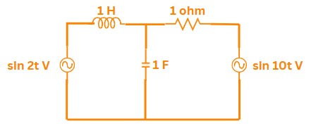
Solution:
Given:
Current source: \( 4\angle90^\circ \) A
Impedances: \( j6 , \Omega \) (inductor) and \( -j3 , \Omega \) (capacitor) in parallel
\(\Rightarrow\) First, calculate the total parallel impedance:
\(Z_{\text{total}} = \frac{(j6)(-j3)}{j6 - j3} = \frac{18}{j3} = -j6 \, \Omega\)
\(\Rightarrow\) Next, compute the output voltage using Ohm's Law:
\(V_o = I \times Z_{\text{total}} = (4\angle90^\circ) \times (6\angle-90^\circ) = 24\angle0^\circ \, \text{V}\)
Correct Ans: B
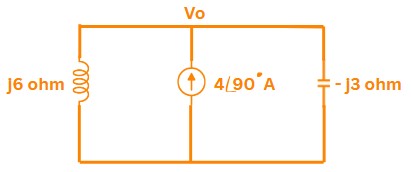
Solution:
\(\Rightarrow\) Step 1: Thevenin Impedance Calculation
\(Z_{th} = -j2\,\Omega \parallel j4\,\Omega\)
\( = \frac{(-j2)(j4)}{-j2 + j4} = \frac{8}{j2} = -j4\,\Omega\)
\(\Rightarrow\) Step 2: Load Impedance for Maximum Power Transfer
\(Z_L = Z_{th}^* = \overline{-j4\,\Omega} = j4\,\Omega\)
Correct Ans: D
Solution:
Imaginary part of impedance: \(\textbf{Reactance}\). Conductance/Admittance are real parts.
Correct Ans: D
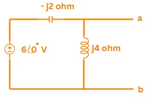
Solution:
\(\text{Given:}\)
\(P = 500\, \text{W}\)
\(\theta = 60^\circ\)
\(\text{In a power triangle, } \tan(\theta) = \frac{BC}{AB}\)
\(\text{Substituting the values:}\)
\(\tan(60^\circ) = \frac{BC}{500}\)
\(\text{We know that } \tan(60^\circ) = \sqrt{3} \approx 1.732\)
\(\text{Thus,}\)
\(1.732 = \frac{BC}{500}\)
\(\text{Multiplying both sides by 500:}\)
\(BC= 1.732 \times 500\)
\(BC= 866\, \text{VAR}\)
\(\text{Since the angle is positive, it indicates a lagging reactive power.}\)
\(BC= 866\, \text{VAR lagging}\)
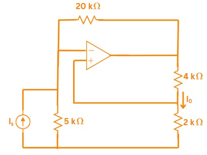
Correct Ans: A
Solution:
\(\Rightarrow\) Voltage at the non-inverting input
\(\quad \quad V^+ = V_{out} \times\frac{2\:k\Omega}{2\:k\Omega + 4 \:k\Omega} = \frac{1}{3} V_{out}\)
\(\Rightarrow\) For ideal op-amp \(V^+ = V^- = \frac{1}{3} V_{out}\)
\(\Rightarrow\) KCL at the inverting node
\(\quad \quad I_o = \frac{V^- - 0}{2\:k\Omega}=\frac{V^-}{2\:k\Omega}\)
\(\Rightarrow\) As per Kirchhoff’s current law at the inverting node, the current injected by the source \(I_s\) must be balanced by the feedback current through the 20 kΩ resistor.
\(\quad \quad I_s +\frac{V_{out} - V^-}{20\:k\Omega} = 0\)
\(\implies I_s = -\frac{3V^- - V^-}{20\:k\Omega} = - \frac{V^-}{10\:k\Omega} \)
\(\Rightarrow\) Combining the above results to find the current gain
\(\quad \:\: \frac{I_o}{I_s} = \frac{\frac{V_s}{2\:k\Omega}}{-\frac{V_s}{10\:k\Omega}} = -5\)
Correct Ans: B
Solution:
\(\Rightarrow\) According to the Gujarat Small Hydel Policy, 2016: Micro Hydel projects are defined as projects with a capacity up to 100 kW.
\[
\therefore { \text{Micro Hydel Capacity} \leq 100\ \text{kW} }
\]
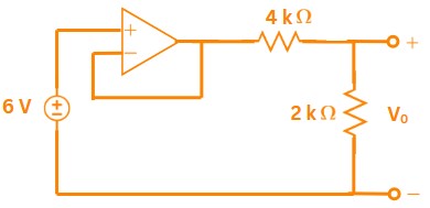
Correct Ans: C
Solution:
\(\Rightarrow\) Since the op-amp is wired as a voltage follower, \(V_{out} = V^+ = 6\:V\)
\(\Rightarrow\) The \(4 k\Omega\) and \(2 k\Omega\) form a simple divider from \(V_{out}\) to ground.
\(\implies V_o = V_{out} \: \frac{2 k\Omega}{4 k\Omega+2 k\Omega} = 2V\)
\(\Rightarrow\) Therefore power absorbed by \(4 k\Omega\) resistor\( = \frac{V^2}{R} = \frac{(6-2)^2}{4000} = 4\:mW\)
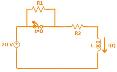
Correct Ans: B
Solution:
\(\Rightarrow\) Initial Condition (\(t < 0>
\( I(0^-) = \frac{V}{R_1} = \frac{20}{R_1} \)
\( I(0^+) = I(0^-) = \frac{20}{R_1} \)
\(\Rightarrow\) Current [removed]\(t > 0\)):
\( i(t) = 2.5 + 1.5e^{-4t} \)
At \( t = 0^+ \):
\( i(0^+) = 2.5 + 1.5 = 4 \) A
Solving for \( R_1 \):
\( \frac{20}{R_1} = 4 \) \(\implies\) \( R_1 = 5\,\Omega \)
\(\Rightarrow\) Steady-State Solution (\(t \to \infty\)):
\( i(\infty) = 2.5 = \frac{20}{R_1 + R_2} \)
\( 2.5 = \frac{20}{5 + R_2} \) \(\implies\) \( R_2 = 3\,\Omega \)
Correct Ans: C
Solution:
Damping factor \(\zeta = 1 = \frac{R}{2}\sqrt{\frac{C}{L}} \Rightarrow R = 2\ \Omega\).
Correct Ans: C
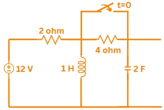
Solution:
For the circuit at \( t = 0^- \):
1. Capacitor \(\rightarrow\) open circuit
2. Inductor \(\rightarrow\) short circuit
Equivalent circuit:
\( 12V \) in series with \( 2\Omega \) and \( 4\Omega \)
Inductor shorts across \( 4\Omega \) resistor
Voltage divider:
\( V_C(0^-) = 12 \times \frac{4}{2+4} \)
\( V_C(0^-) = 12 \times \frac{2}{3} \)
\( V_C(0^-) = 8V \)
Correct Ans: A
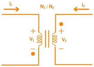
Solution:
For an ideal transformer:
The voltage ratio equals the turns ratio:
\( \frac{V_2}{V_1} = \frac{N_2}{N_1} \)
Given turns ratio:
\( \frac{N_2}{N_1} = 10 \)
Thus:
\( \frac{V_2}{V_1} = 10 \)
Correct Ans: C
Solution:
Given parameters:
- Short-circuit current (\(I_{sc}\)) = 30 A
- Open-circuit voltage (\(V_{oc}\)) = 12 V
- Load resistance (\(R_L\)) = \(2\Omega\)
\(\Rightarrow\) Find internal resistance (\(R_{int}\)):
\( R_{int} = \frac{V_{oc}}{I_{sc}} = \frac{12}{30} = 0.4\,\Omega \)
\(\Rightarrow\) Total circuit resistance:
\( R_{total} = R_{int} + R_L = 0.4 + 2 = 2.4\,\Omega \)
\(\Rightarrow\) Current through circuit:
\( I = \frac{V_{oc}}{R_{total}} = \frac{12}{2.4} = 5\,A \)
\(\Rightarrow\) Power delivered to load:
\( P = I^2 R_L = (5)^2 \times 2 = 50\,W \)
Correct Ans: C
Solution:
\(\Rightarrow\) Statement 1: True. LED efficiency is higher than incandescent lamps because less energy is wasted as heat. The efficiency can be represented as \(\eta_{LED} = \frac{P_{light}}{P_{total}} \approx 90\%\) compared to \(\eta_{incandescent} \approx 10\%\).
\(\Rightarrow\) Statement 2: True. LED drivers convert AC to DC and regulate current, generating heat \(P_{loss} = I^2R_{driver}\).
Correct Ans: B
Solution:
\(\Rightarrow\) In Parallel MTDC systems, power flow reversal is achieved electronically by changing current direction through converters. The power equation is \(P = V_{dc} \times I_{dc}\). Unlike Series MTDC, no mechanical switches are needed.
Correct Ans: C
Solution:
\(\Rightarrow\) Statement 1: True. In parallel MTDC, valve voltage rating scales with power: \(V_{valve} \propto P\) because converters share current.
\(\Rightarrow\) Statement 2: True. In series MTDC, valve current rating scales with power: \(I_{valve} \propto P\) because converters share voltage.
Correct Ans: B
Solution:
\(\Rightarrow\) Series MTDC uses current control where one converter acts as the current regulator (\(I_{ref}\)). Other converters adjust their voltages to maintain this current, following \(P = I_{ref} \times V_{dc}\).
Correct Ans: C
Solution:
\(\Rightarrow\) DC lines are limited by the conductor's thermal capacity. The maximum power is given by \(P_{max} = I_{thermal}^2 \times R_{conductor}\), where \(I_{thermal}\) is the maximum allowable current before overheating.
Correct Ans: D
Solution:
\(\Rightarrow\) Statement 1: False. Ground impedance exists in DC systems and is non-zero: \(Z_{ground} = R_{ground} + j\omega L_{ground}\) (though \(\omega = 0\) for DC, resistance remains).
\(\Rightarrow\) Statement 2: False. Mono-polar HVDC systems are common, using one conductor with ground return: \(P = V_{-} \times I_{ground}\).
Correct Ans: D
Solution:
\(\Rightarrow\) Homopolar HVDC uses multiple conductors at the same polarity (typically negative \(V_{-}\)) and always requires a ground/metallic return path for current \(I_{return}\).
Correct Ans: A
Solution:
\(\Rightarrow\) For a 6-pulse, three-phase Graetz bridge the average DC voltage is : \(V_{dc} = \frac{3\sqrt{2}}{\pi}\;V_{LL}\;\cos(\alpha)\)
\(\implies V_{dc} = 1.35 \times 400\:kV\times\cos(45)\)
\(\implies V_{dc} = 382 \:kV\)
Correct Ans: C
Solution:
\(\Rightarrow \:h_{\mathrm{ac, dominant}} = 12k \pm 1 \quad\Longrightarrow\quad 11^\mathrm{th}\text{ and }13^\mathrm{th}\)
\(\Rightarrow h_{\mathrm{dc, dominant}} = 12k
\quad\Longrightarrow\quad12^\mathrm{th}\)
Correct Ans: B
Solution:
\(\Rightarrow\) For three level NPC, \( m = 3 \)
\(\quad \rightarrow \text{DC‐link capacitors} = m-1 = 2 \)
\(\quad \rightarrow \text{Switching devices per phase} = 2 (m-1) = 4\)
\(\quad \rightarrow \text{Clamping diodes per phase} = (m-1)(m-2) = 2\)
Correct Ans: C
Solution:
\(\Rightarrow\) Under normal HVDC operation the rectifier is operated in constant‐current (CC) mode and the inverter in constant‐extinction‐angle (CEA) mode to achieve good voltage regulation. Swapping these (i.e. doing CC at the inverter while holding minimum γ at the rectifier) is not the standard practice for voltage control.
\(\Rightarrow\) So statement 1 is false.
\(\Rightarrow\) One of the primary roles of constant‐current control at the rectifier is to limit the maximum DC current (e.g. during AC or DC faults) to protect valves and limit fault currents.
\(\Rightarrow\) So statement 2 is true.
Correct Ans: A
Solution:
\(\Rightarrow\) The inverter’s extinction angle must never fall below a minimum value to ensure that each valve has fully commutated before the next firing — this avoids commutation failures.
\(\Rightarrow\) So statement 1 is true.
\(\Rightarrow\) Constant-extinction-angle (CEA) control indeed shows a negative-resistance characteristic: as DC voltage demand rises, the AC system voltage falls, which can make the control loop unstable if the AC network is weak.
\(\Rightarrow\) So statement 2 is true.
Correct Ans: D
Solution:
\(\Rightarrow \bf {\text{Reduce commutation failures:}}\) The smoothing reactor’s inductance helps sustain DC current during brief AC‐voltage dips at the inverter bus, ensuring valves have sufficient overlap voltage to complete commutation.
\(\Rightarrow \bf {\text{Avoid discontinuous current at light loads:}}\) By providing stored energy (inductance), the reactor keeps the DC current from dropping to zero when the load is light.
\(\Rightarrow \bf {\text{Reduce DC harmonics:}}\) The high‐value inductance filters out the 300 Hz (6-pulse) or 600 Hz (12-pulse) ripple components, lowering DC‐side harmonic content.
Correct Ans: B
Solution:
\(\Rightarrow \bf {\text{Statement 1 is True:}}\)
\(\quad\rightarrow\)
The voltage‐setting terminal (VST) in an HVDC link must actively regulate its AC bus voltage.
\(\quad\rightarrow\) If that bus voltage dips, the converter at the VST is the one that directly fights the dip to maintain its setpoint.
\(\quad\rightarrow\) Consequently, voltage instability on the AC side manifests most severely at the VST, since all voltage‐regulation action is centered there and commutation can fail if the voltage falls too low.
\(\Rightarrow \bf {\text{Statement 2 is false:}}\)
\(\quad\rightarrow\) Simply applying constant AC‐voltage control at the VST does not automatically stabilize the entire link.
\(\quad\rightarrow\) In multi‐terminal or two‐terminal HVDC systems, the controls at both ends interact, and without coordination improper or conflicting setpoints can actually degrade stability elsewhere in the network.
Correct Ans: A
Solution:
Correct Ans: D
Solution:
\(\Rightarrow\)The typical ELV range is up to 50 V AC and up to 120 V DC
Correct Ans: B
Solution:
\(\Rightarrow\) A classic example of a positive-pressure room is the \(\bf\text{Intensive Care Unit (ICU). }\)
\(\Rightarrow\) It’s kept at slightly higher pressure than adjacent spaces so that any leakage is outwards, helping to keep contaminants from entering the patient area.
Correct Ans: A
Solution:
\(\Rightarrow\) A Pitot tube is a simple but very important instrument widely used in fire-fighting systems.
Statement-1: This is an instrument for the measurement of water velocity pressure.
\(\rightarrow\) A Pitot tube measures the velocity pressure of the water flow.
\(\rightarrow\) It works by capturing the flowing water directly into a tube, which causes the water to slow down (almost to zero velocity at the tip) and build up a pressure known as stagnation pressure.
\(\rightarrow\) This stagnation pressure is related to the flow velocity using Bernoulli’s principle:
\[
v = \sqrt{2 \times \dfrac{P}{\rho}}
\]
Where:
\( v \) = velocity of water (m/s),
\( P \) = velocity pressure (N/m²),
\( \rho \) = density of water (approximately \( 1000 \, \text{kg/m}^3 \)).
\(\therefore\) The Pitot tube directly measures the pressure due to water velocity.
Statement-2: This can be used to determine approximate amount of water flowing with the help of size of opening (orifice/nozzle) and water velocity pressure.
\(\rightarrow\) Once the velocity is known using the Pitot tube, and the area (\( A \)) of the nozzle or opening is known, the flow rate \( Q \) can be calculated using the formula:
\[
Q = A \times v
\]
Where:
\( Q \) = flow rate (m³/s),
\( A \) = cross-sectional area of nozzle/orifice (m²),
\( v \) = velocity of water (m/s).
\(\therefore\) By knowing water velocity and opening size, easily estimate the quantity of water flowing.
Correct Ans: C
Solution:
Statement-1: The frequencies of these dynamic forces are independent on the speed of the pump.
\(\rightarrow\) In a vertical firefighting water pump, hydraulic turbulence and dynamic forces are highly dependent on the speed of the pump.
\(\rightarrow\) When the pump rotates faster, the water flow patterns and turbulence inside the pump also change their behavior.
\(\rightarrow\) Turbulence-induced forces and their frequencies vary with RPM (revolutions per minute) of the pump shaft.
\(\rightarrow\) The forcing frequency is often proportional to the rotational speed.
\(\implies\) Ex.: If the pump runs at a speed \( N \) (in rpm), then forcing frequency \( f \) can be:
\[
f = \dfrac{N}{60}
\]
\(\therefore\) Statement-1 is False.
Statement-2: When the frequency of dynamic forces matches the natural frequency of a pump component, the resonant vibration will occur.
\(\rightarrow\) Resonance occurs when the forcing frequency matches the natural frequency (\( f_n \)) of the system or component.
\(\rightarrow\) At resonance, even a small periodic force can produce large amplitude vibrations, which can severely damage the pump.
\(\rightarrow\) Resonance condition is:
\[
f_{\text{forcing}} = f_{\text{natural}}
\]
where:
\( f_{\text{forcing}} \) = Frequency of external dynamic force
\( f_{\text{natural}} \) = Natural frequency of the structure
\(\therefore\) Statement-2 is True.
Correct Ans: A
Solution:
\(\Rightarrow\) In a CCTV system, especially with IP (Internet Protocol) cameras, the cameras capture video footage and send it digitally (through a network — LAN or Wi-Fi) to the NVR (Network Video Recorder).
\(\Rightarrow\) Main Role of NVR:
\(\rightarrow\) It receives, processes, and most importantly, stores video footage from IP cameras.
\(\rightarrow\) It allows playback, live view, and recording management of multiple cameras simultaneously.
\(\implies\) The primary function of an NVR is Storing video footage from IP cameras.
Correct Ans: C
Solution:
\(\Rightarrow\) Every pump has a Best Efficiency Point (BEP) — the flow rate at which it operates most efficiently.
\(\Rightarrow\) Running the pump at or near its BEP ensures:
\(\rightarrow\) Less vibration
\(\rightarrow\) Minimum wear on components
\(\rightarrow\) Lower energy consumption
\(\rightarrow\) Reduced chances of cavitation
\(\implies\) When operating at BEP, the pump runs with minimum hydraulic losses, maintaining smooth flow:
\[
\eta_{\text{pump}} = \dfrac{P_{\text{output}}}{P_{\text{input}}}
\]
where:
\( \eta_{\text{pump}} \) = Pump efficiency
\( P_{\text{output}} \) = Hydraulic power delivered
\( P_{\text{input}} \) = Power supplied to pump
\(\therefore\) Continuous operation near maximum efficiency capacity = longer pump life.
Correct Ans: D
Solution:
Option (A):
\(\rightarrow\) In case of a major fire, the diesel engine running the fire pump must work without interruption.
\(\rightarrow\) The fuel storage must be enough to cover the entire firefighting operation duration plus some extra (safety factor) for uncertainties.
Option (B):
\(\rightarrow\) Suppose the firewater storage tank cannot be refilled quickly; the diesel engine must keep running until all the available firewater is used up.
\(\rightarrow\) So, the fuel quantity must match the maximum expected pump operation time.
Option (C):
\(\rightarrow\) According to fire protection standards (like NFPA 20), the minimum onsite diesel fuel storage should be:
\[
\text{Fuel Storage} \geq 5.07\ \text{liters per kilowatt (or 1 gal per horsepower)}
\]
\(\rightarrow\) This ensures the pump can run for a long minimum duration even without refueling.
\(\implies\) Relation:
If the pump motor has:
\(\rightarrow\) Power rating = \( P_{\text{kW}} \) kilowatts,
then minimum fuel required:
\[
\text{Minimum Fuel Volume} = 5.07 \times P_{\text{kW}}\ (\text{liters})
\]
\(\therefore\) All above options are True.
Correct Ans: B
Solution:
Statement-1: BMS is a computer-based control system that controls and monitors the mechanical and electrical equipment in buildings.
\(\Rightarrow\) A Building Management System (BMS) monitors and controls important services like:
\(\rightarrow\) HVAC (Heating, Ventilation, and Air Conditioning),
\(\rightarrow\) Lighting,
\(\rightarrow\) Power Systems,
\(\rightarrow\) Fire Systems,
\(\rightarrow\) Security Systems.
\(\Rightarrow\) BMS helps optimize energy usage, improve occupant comfort, and ensure building safety.
\(\therefore\) Statement-1 is correct.
Statement-2: BMS connects the building services plant back to a central computer to enable the control of on/off times of lighting systems excluding HVAC system.
\(\rightarrow\) BMS does not exclude HVAC systems.
\(\rightarrow\) Controlling HVAC is one of the main roles of BMS because HVAC systems are major energy consumers in a building.
\(\Rightarrow\) BMS controls both:
\(\rightarrow\) Lighting (on/off schedules, dimming)
\(\rightarrow\) HVAC (temperature, humidity, air flow, energy optimization)
\(\therefore\) Statement-2 is incorrect.
Correct Ans: A
Solution:
\(\Rightarrow\) Pascal's Pressure Principle:
\(\rightarrow\) States that when pressure is applied at any point in a confined fluid, it is transmitted equally in all directions throughout the fluid (like car brakes, lifts, etc.)
\(\implies Ex.\)
If force \( F_1 \) is applied on a small piston of area \( A_1 \), then pressure \( P \) generated is:
\[
P = \frac{F_1}{A_1}
\]
Since pressure is transmitted equally:
\[
P = \frac{F_2}{A_2}
\]
\[\therefore
F_2 = F_1 \times \frac{A_2}{A_1}
\]
\(\rightarrow\) Where \( F_2 \) is the output lifting force generated on a larger piston (area \( A_2 \)).
\(\rightarrow\) This allows a small force to lift a large weight — the working principle of a hydraulic lift.
Correct Ans: B
Solution:
\(\Rightarrow\) NFPA 780 is specifically focused on protection against lightning hazards.
\(\rightarrow\) It provides guidelines on:
- Designing Lightning Protection Systems (LPS),
- Protecting structures (buildings, towers, tanks) from lightning strikes,
- Reducing risk of fire, explosions, and electrical surges caused by lightning.
\(\rightarrow\) It covers parts like:
- Air terminals (lightning rods),
- Conductors (metallic paths for lightning current),
- Grounding systems (to safely dissipate energy into the earth).
Correct Ans: C
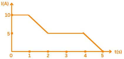
Solution:
\(\Rightarrow\) 1. From \( t = 0 \, \text{s} \) to \( t = 1 \, \text{s} \):
The current is constant at \( I = 10 \, \text{A} \).
\[
Q_1 = I \times \Delta t = 10 \, \text{A} \times 1 \, \text{s} = 10 \, \text{C}
\]
2. From \( t = 1 \, \text{s} \) to \( t = 2 \, \text{s} \):
The current linearly decreases from \( 10 \, \text{A} \) to \( 5 \, \text{A} \). The average current during this time is:
\[
\text{Average current} = \frac{10 + 5}{2} = 7.5 \, \text{A}
\]
\[
Q_2 = \text{Average current} \times \Delta t = 7.5 \, \text{A} \times 1 \, \text{s} = 7.5 \, \text{C}
\]
3. From \( t = 2 \, \text{s} \) to \( t = 3 \, \text{s} \):
The current is constant at \( 5 \, \text{A} \).
\[
Q_3 = I \times \Delta t = 5 \, \text{A} \times 1 \, \text{s} = 5 \, \text{C}
\]
Total charge:
\[
Q_{\text{total}} = Q_1 + Q_2 + Q_3 = 10 \, \text{C} + 7.5 \, \text{C} + 5 \, \text{C} = 22.5 \, \text{C}
\]
Correct Ans: B
Solution:
\(\Rightarrow\) The given differential equation is:
\[
\frac{d^2 v_c}{dt^2} + \frac{dv_c}{dt} + v_c = V_s u(t)
\]
This is a second-order linear differential equation of the form:
\[
\frac{d^2 y}{dt^2} + 2 \zeta \omega_n \frac{dy}{dt} + \omega_n^2 y
\]
By comparing the coefficients, we get:
\[
\omega_n = 1, \quad \zeta = \frac{1}{2}
\]
Since \( \zeta = \frac{1}{2} \) (which is less than 1), the system is underdamped.
Correct Ans: c
Solution:
\(\Rightarrow\) Given:
- Voltage: \( v = 628 \sin(314t + 45^\circ) \)
- Current: \( i = 10 \sin(314t - 45^\circ) \)
\(\Rightarrow\) Convert to Phasors (RMS):
\[
V = \frac{628}{\sqrt{2}} \angle 45^\circ = 444.1 \angle 45^\circ \, \text{V}
\]
\[
I = \frac{10}{\sqrt{2}} \angle -45^\circ = 7.07 \angle -45^\circ \, \text{A}
\]
\(\Rightarrow\) Calculate Impedance (\( Z \)):
\[
Z = \frac{V}{I} = \frac{444.1 \angle 45^\circ}{7.07 \angle -45^\circ} = 62.8 \angle 90^\circ \, \Omega
\]
\(\Rightarrow\) Identify Element:
- \( \angle 90^\circ \implies \) \textbf{Inductor} (\( X_L = 62.8 \, \Omega \)).
\(\Rightarrow\) Find Inductance (\( L \)):
\[
X_L = \omega L \implies 62.8 = 314 \, L \implies L = 0.2 \, \text{H} = 200 \, \text{mH}
\]
\(\implies\) Inductor, 200 mH
Correct Ans: A
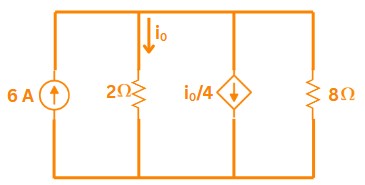
Solution:
\(\Rightarrow\) Using nodal analysis:
current \(i_o=1\: A\)
\(\implies\) Power = 8 W
Correct Ans: B
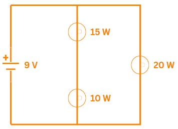
Solution:
\(\Rightarrow\) - Total power: \(P_{total} = 10 + 15 + 20 = 45\:W\)
- Battery current: \(I = \frac{P_{total}}{V} = \frac{45}{9} = 5\:A\)
- Current through \(10\:W\) bulb: \(I_{10} = \frac{25}{9} = 2.78\:A\)
Correct Ans: B
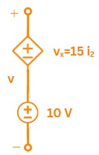
Solution:
\(\Rightarrow\) Applying KVL to the branch:
\(v = 15 \times (- 2) + 10 = -30+10 = -20\:V\)
Correct Ans: C
Solution:
\(\Rightarrow\) - Step response: \(Y(s) = \frac{2}{s} - \frac{1}{s+1}\)
- Transfer function: \(H(s) = \frac{Y(s)}{U(s)} = \frac{s+2}{s+1}\)
Correct Ans: D
Solution:
\(\Rightarrow\) For stability, both margins must be positive:
- Gain Margin (GM): \(\text{GM} > 0\:dB\)
- Phase Margin (PM): \(\text{PM} > 0^\circ\)
Correct Ans: C
Solution:
\(\Rightarrow\) \(\Rightarrow\) Statement 1: False. Negative feedback improves stability but doesn't guarantee it (e.g., high gain can cause oscillations).
\(\Rightarrow\) Statement 2: True. Negative feedback reduces sensitivity to parameter variations (\(\Delta T/T \approx 0\) for large loop gain).
Correct Ans: B
Solution:
\(\Rightarrow\) \(\Rightarrow\) Statement 1: True. A PI controller adds an integrator, increasing system order (e.g., from 1st to 2nd order).
\(\Rightarrow\) Statement 2: False. Increasing integral gain \(K_i\) reduces damping, causing higher overshoot (\(\zeta \propto \frac{1}{K_i}\)).
Correct Ans: A
Solution:
\(\Rightarrow\) Standard definitions:
- Controllability: State \(X(t)\) can be driven to any desired value using input \(u(t)\).
- Observability: State \(X(t_0)\) can be determined from output \(y(t)\).
Correct Ans: A
Solution:
\(\Rightarrow\) Transfer function derived from state-space matrices:
\(T(s) = C(sI - A)^{-1}B + D = \frac{8s + 1}{s^2 + 8}\)
Correct Ans: B
Solution:
\(\Rightarrow\) For a 4th-order system with 2 zeros:
High-frequency slope = \(-20 \times (\text{poles} - \text{zeros}) = -20 \times (4 - 2) = -40\:dB/decade\)
Correct Ans: B
Solution:
\(\Rightarrow\) Gain Margin is inversely proportional to gain:
\(\text{GM} = \frac{1}{ G(j\omega_c) })\)
\(\therefore\) Doubling K halves GM
Correct Ans: C
Solution:
\(\Rightarrow\) Initial Value Theorem:
\(y(0) = \lim_{s \to \infty} sY(s) = \lim_{s \to \infty} \frac{6se^{-2s}}{s+4} = 0\) (since \(e^{-2s}\) dominates).
Correct Ans: C
Solution:
Statement 1: Minimization of integral of squared error should be considered as design criteria when error magnitude is very small (typically lesser than 0.1).
\(\Rightarrow\) The Integral of Squared Error (ISE):
\[
\text{ISE} = \int_0^\infty e^2(t)\,dt
\]
\(\rightarrow\) Squaring small errors makes them even smaller, reducing their impact.
\(\rightarrow\) ISE is better at penalizing large errors (due to squaring), not suitable when errors are already very small.
\(\implies\) False
Statement 2:
Minimization of integral of time-weighted absolute error should be considered as design criteria when error persists for longer time.
\(\rightarrow\) The Integral of Time-weighted Absolute Error (ITAE):
\[
\text{ITAE} = \int_0^\infty t\,|e(t)|\,dt
\]
\(\rightarrow\) The time multiplier gives more weight to errors that occur later (i.e., persistent errors).
\(\therefore\) ITAE is ideal for reducing long-lasting or slow-decaying errors.
\(\therefore\) True
Correct Ans: C
Solution:
\(\Rightarrow\) Branches to infinity = Number of poles (\(3\)) - Number of zeros (\(1\)) = \(2\).
Correct Ans: A
Solution:
Given:
- Transfer function of the system:
\( G(s) = \frac{10}{s + 5} \)
- Proportional controller gain:
\( K_p = 2 \)
- Reference input:
\( R(s) = \frac{5}{s} \)
Closed-loop transfer function:
\[
T(s) = \frac{G(s) \cdot K_p}{1 + G(s) \cdot K_p} = \frac{\frac{20}{s + 5}}{1 + \frac{20}{s + 5}} = \frac{20}{s + 25}
\]
Error transfer function:
\[
E(s) = R(s) \left( 1 - T(s) \right) = \frac{5}{s} \left( 1 - \frac{20}{s + 25} \right) = \frac{5(s + 5)}{s(s + 25)}
\]
Steady-state error (using Final Value Theorem):
\[
\text{Steady-state error} = \lim_{s \to 0} s \cdot E(s) = \lim_{s \to 0} \frac{5(s + 5)}{s + 25} = 1
\]
Thus, the steady-state error is \( 1 \).
Correct Ans: B
Solution:
\(\Rightarrow\) \(\Rightarrow\) Statement 1: True. Derivative control (\(K_d s\)) improves transient response by damping oscillations.
\(\Rightarrow\) Statement 2: False. Integral control (\(K_i/s\)) eliminates steady-state error (\(e_{ss} \to 0\)).
Correct Ans: C
Solution:
\(\Rightarrow\) Damping ratio for \(G(s) = \frac{K}{s(s+1)}\):
\(\zeta = \frac{1}{2\sqrt{K}}\) → As \(K \to \infty\), \(\zeta \to 0\) (undamped oscillations).
Correct Ans: C
Solution:
\(\Rightarrow\) Resonance frequency for \(G(s)H(s) = \frac{16}{s^2 + 4s}\):
\(\omega_r = \omega_n \sqrt{1 - 2\zeta^2} = 2\sqrt{2} \times \sqrt{1 - 2(0.5)^2} = 2\:rad/sec\)
Correct Ans: C
Solution:
\(\Rightarrow\) Transfer function is the ratio of output to input Laplace transforms:
\(T(s) = \frac{\mathcal{L}\{\delta(t)\}}{\mathcal{L}\{u(t)\}} = \frac{1}{1/s} = s\)
Correct Ans: B
Solution:
\(\Rightarrow\) Centroid for root locus:
\(\sigma = \frac{\sum \text{poles} - \sum \text{zeros}}{\text{poles} - \text{zeros}} = \frac{(0 - 2 - 2) - (-2)}{3 - 1} = -\frac{2}{3}\)
Correct Ans: B
Solution:
\(\Rightarrow\) Characteristic equation: \(z^3 - 0.81z = 0 \implies \) Roots at \(z = 0, \pm 0.9\).
\(\therefore\) Poles on unit circle \(( z = 0.9)\) imply marginal stability.
Correct Ans: B
Solution:
\(\Rightarrow\) Maximum overshoot depends only on damping ratio (\(\zeta\)), which is independent of \(K\) for \(G(s) = \frac{K}{Js^2 + Bs}\). Other specs (rise time \(t_r\), settling time \(t_s\)) vary with \(K\).
Correct Ans: A
Solution:
\(\Rightarrow\) For separately excited DC motor:
\[
N \propto \frac{V - I_a R_a}{ \phi}
\]
Where:
\(\rightarrow\) \( N \) = Speed of motor (rpm)
\(\rightarrow\) \( V \) = Supply voltage (V)
\(\rightarrow\) \( I_a \) = Armature current (A)
\(\rightarrow\) \( R_a \) = Armature resistance (Ω)
\(\rightarrow\) \( \phi \) = Flux per pole (Wb)
1. Changing Field Current \(\implies \) changing Flux \( \phi \)):
\(\rightarrow\) \( N \propto \frac{1}{\phi} \), decreasing the flux (reducing field current) increases speed, and increasing flux reduces speed.
2. Changing Supply Voltage \( V \):
\(\rightarrow\) Speed \( N \) is directly proportional to the supply voltage \( V \) (neglecting \( I_a R_a \) for small \( R_a \)).
\(\rightarrow\) Increasing \( V \) increases the numerator, increasing speed; decreasing \( V \) decreases speed.
3. Changing Armature Resistance \( R_a \):
\(\rightarrow\) Increasing \( R_a \) increases the voltage drop \( I_a R_a \), thus reducing the effective voltage across the armature and decreasing speed.
\(\rightarrow\) This method is mainly used to control speed under loaded conditions (called armature resistance control method), but it causes power loss due to heating (not efficient).
Correct Ans: A
Solution:
\(\Rightarrow\) Assertion: DC series motors are suitable for electric locomotives.
True — Their high torque characteristic makes them ideal for traction applications like electric trains.
\(\Rightarrow\) Reason: DC series motors provide high starting torque.
True — Due to \(T \propto I_{a}^{2}\), they deliver high torque at low speed.
\(\therefore\) Reason is the correct explanation for Assertion — The high starting torque is the main reason why DC series motors are used in electric locomotives.
Correct Ans: B
Solution:
\(\Rightarrow\) For DC generator :
\[
E = V + I_a R_a
\Rightarrow I_a = \frac{E - V}{R_a}
\]
\[\implies
I_a = \frac{240 - 220}{0.25} = \frac{20}{0.25} = 80\ \text{A}
\]
\(\rightarrow\) Variable Losses which equal stray losses at maximum efficiency:
\[
\therefore Stray \: losses = I_a^2 R_a = (80)^2 \times 0.25 = 1600\ \text{W}
\]
Correct Ans: D
Solution:
\[
\begin{array}{|c|c|}
\hline
\textbf{Transformer Connection} & \textbf{Phase Shift (Primary to Secondary)} \\
\hline
\text{Star--Star (Y--Y)} & 0^\circ\ (\text{No phase shift}) \\
\hline
\text{Delta--Delta (\(\Delta--\Delta\))} & 0^\circ\ (\text{No phase shift}) \\
\hline
\text{Star--Delta (Y--\(\Delta)\)} & +30^\circ\ (\text{Secondary leads Primary}) \\
\hline
\text{Delta--Star (\(\Delta\)--Y)} & -30^\circ\ (\text{Secondary lags Primary}) \\
\hline
\text{Delta--Zigzag} & \text{Depends on winding configuration} \\
\hline
\end{array}
\]
Correct Ans: A
Solution:
\(Given\): Two winding transformer: 200 V/100 V, 1000 VA.
\(\therefore\) Rated current in 200 V winding \(I_{ab}= \frac{1000}{200} = 5 A\)
\(\therefore\) Rated current in 100 V winding \(I_{bc}= \frac{1000}{100} = 10 A\)
\(\implies\) Auto-transformer : 100 V/300 V. Consider given figure.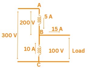
\(\therefore V_h=100+200=300 V, \quad V_l=100 V\)
\(\implies I_{load} = I_{ab}+ I_{bc}=5+10=15 A\)
\(\therefore\) Rating of Auto transformer \(=\frac{V_l \times I_{load}}{1000} = \frac{100 \times 15}{1000}=1.5 kVA\)
Correct Ans: C
Solution:
\(\Rightarrow\) Voltage regulation is approximately given by:
\[
\text{Regulation} = I_2 \left( R_{eq} \cos\theta + X_{eq} \sin\theta \right)
\]
\(\implies\) For zero voltage regulation:
\[
R_{eq} \cos\theta + X_{eq} \sin\theta = 0
\]
\[
\cos\theta + \left( \frac{X_{eq}}{R_{eq}} \right) \sin\theta = 0
\]
\[
\Rightarrow \tan\theta = -\frac{R_{eq}}{X_{eq}}
\]
\(\therefore\) This condition is only possible when \( \theta < 0 \) ⇒ leading power factor.
Correct Ans: D
Solution:
\(\Rightarrow\) The magnetizing current \( I_m \) in an induction motor is given by:
\[
I_m \propto \frac{g}{\mu_0 A}
\]
Where:
\(\rightarrow\) \( g \) = air-gap length
\(\rightarrow\) \( \mu_0 \) = permeability of free space
\(\rightarrow\) \( A \) = cross-sectional area of the air-gap
\(\therefore\) If air-gap \( g \) is small, then magnetizing current \( I_m \) is reduced.
Correct Ans: B
Solution:
\(\Rightarrow\) The starting torque \( T_s \) of an induction motor is proportional to the square of the applied voltage:
\[
T_s \propto V^2
\]
\(\rightarrow\) \(T_{old} =V \), and the reduced voltage be \( T_{new}=\frac{V}{2} \).
\[
\frac{T_{\text{new}}}{T_{\text{original}}} = \left( \frac{V/2}{V} \right)^2 = \left( \frac{1}{2} \right)^2 = \frac{1}{4}
\]
Correct Ans: B
Solution:
\[
N_s = \frac{120 \times f}{P} = \frac{120 \times 60}{8} = 900 \text{ rpm}
\]
\[\rightarrow
f_r = s \cdot f_s \Rightarrow s = \frac{f_r}{f_s} = \frac{2}{60} = \frac{1}{30}
\]
\[\therefore
N_r = (1 - s) \cdot N_s = \left(1 - \frac{1}{30}\right) \cdot 900 = \frac{29}{30} \cdot 900 = 870 \text{ rpm}
\]
Correct Ans: D
Solution:
\(\Rightarrow\) To synchronize an incoming alternator, the three essential conditions are:
1. Same Voltage Magnitude:
\[
|V_{\text{incoming}}| = |V_{\text{bus}}|
\]
2. Same Frequency:
\[
f_{\text{incoming}} = f_{\text{bus}}
\]
3. Same Phase Sequence: R-Y-B with R-Y-B.
\(\therefore\) Above are mandatory for proper synchronization.
\(\Rightarrow\) Same Prime Mover Speed is not a necessary condition.
\(\rightarrow\) Speed affects frequency, but if the frequency is already matched, the exact speed match is not required.
\(\rightarrow\) The speed will adjust slightly based on load once synchronized.
Correct Ans: B
Solution:
\(\Rightarrow\) The reactive power (\(Q\)) output of a synchronous generator depends primarily on the excitation level, i.e., the DC field current.
\(\rightarrow\) For a synchronous generator connected to an infinite bus:
\[
Q \propto (E - V)
\]
Where:
\(\rightarrow\) \(E\) = Internal generated EMF (depends on excitation)
\(\rightarrow\) \(V\) = Terminal voltage (constant for infinite bus)
\(\implies\) If excitation increases, \(E > V\), generator supplies reactive power (over-excited).
\(\implies\) If excitation decreases, \(E < V\), generator absorbs reactive power (under-excited).
Correct Ans: C
Solution:
The rms value of induced EMF per phase:
\[
E = 4.44 \, f \, N \, \Phi \, K_p \, K_d
\]
Where:
\(\rightarrow\) \(f\) = Frequency
\(\rightarrow\) \(N\) = Number of turns per phase
\(\rightarrow\) \(\Phi\) = Flux per pole
\(\rightarrow\) \(K_p\) = Pitch factor
\(\rightarrow\) \(K_d\) = Distribution factor
Correct Ans: B
Solution:
\(\Rightarrow\) In rotating electromechanical machines (such as synchronous machines), the developed electromagnetic torque is given by:
\[
T \propto E_f \cdot V \cdot \sin \delta \propto |\mathbf{F}_{\text{stator}}| \cdot |\mathbf{F}_{\text{rotor}}| \cdot \sin(\delta)
\]
Where:
\(\rightarrow\) \( |\mathbf{F}_{\text{stator}}| \) = Strength of stator magnetic field
\(\rightarrow\) \( |\mathbf{F}_{\text{rotor}}| \) = Strength of rotor magnetic field
\(\rightarrow\) \( \delta \) = Torque angle (angle between stator and rotor fields)
Correct Ans: C
Solution:
\(\Rightarrow\) At standstill, a single-phase induction motor produces a pulsating magnetic field, not a rotating one.
\(\rightarrow\) This pulsating field can be mathematically resolved into two equal and opposite rotating magnetic fields, but these do not produce net starting torque.
\(\therefore\) The motor does not start on its own — Assertion is true.
\(\therefore\) The net rotating magnetic field is not zero, rather it’s the torque that is zero due to equal and opposite effects — Reason is false.
Correct Ans: C
Solution:
\[
N_s = \frac{120 \times f}{P} = \frac{120 \times 50}{6} = 1000\ \text{rpm}
\]
\(\therefore\) Slip with respect to backward rotating field:
\[
s_b = \frac{N_s + N_r}{N_s} = \frac{1000 + 950}{1000} = \frac{1950}{1000} = 1.95
\]
Correct Ans: A
Solution:
\(\Rightarrow\) Energy stored in magnetic field:
\[
W = \frac{1}{2} \cdot N \cdot I \cdot \Phi
\]
Where:
\(\rightarrow\) \( W \) = energy stored (Joules)
\(\rightarrow\) \( N \) = number of turns = 1000
\(\rightarrow\) \( I \) = current in amperes = 1 A
\(\rightarrow\) \( \Phi \) = magnetic flux in webers = 1 mWb = \( 1 \times 10^{-3} \) Wb
\[
W = \frac{1}{2} \cdot 1000 \cdot 1 \cdot (1 \times 10^{-3}) = \frac{1}{2} \cdot 1 = 0.5\ \text{J}
\]
Correct Ans: D
Solution:
\(\Rightarrow\) Distributing the winding:
\(\rightarrow\) Reduces space harmonics in the generated EMF.
\(\rightarrow\) Makes the waveform more sinusoidal.
\(\rightarrow\) Reduces distortion and harmonics (like 3rd, 5th harmonics), thereby improving EMF quality.
Correct Ans: A
Solution:
\(\Rightarrow\) In synchronous machines (especially synchronous motors), V-curves are plots showing the variation of armature current \( I_a \) with respect to field (excitation) current \( I_f \) at a constant mechanical load.
Correct Ans: C
Solution:
\(\Rightarrow\) In a split-phase induction motor, there are two windings:
- Main (Running) winding
- Auxiliary (Starting) winding
\(\rightarrow\) To create phase difference between currents in these windings (for starting torque), their electrical characteristics are designed differently:
\(\rightarrow\) The running winding is designed to be highly inductive with low resistance, so that current lags the voltage significantly.
\(\rightarrow\) The starting (auxiliary) winding is designed to have high resistance and low inductance, so that current is more in-phase with voltage.
\(\therefore\) This phase difference (\( \phi \)) between the two winding currents is necessary for producing a rotating magnetic field at startup.
Correct Ans: B
Solution:
\(\mathbf{Assertion}\): The no-load current of an induction motor is usually more than that of a transformer of similar rating.
\(\Rightarrow\) In transformers, the no-load current is very small (\(I_0= 1–3 \% \: \:of \: \:I_{fl}\)).
\(\Rightarrow\) In induction motors, the no-load current is relatively higher (\(I_0= 25–40 \% \: \:of \: \:I_{fl}\)).
This is because the induction motor:
\(\quad \rightarrow\) Has to produce a rotating magnetic field.
\(\quad \rightarrow\) Also has to overcome mechanical losses (like friction and windage) even under no-load conditions.
\(\quad \rightarrow\) Has an air-gap, which increases the magnetizing reactance ⇒ requires more current to magnetize.
\(\mathbf{Reason}\): An induction motor can be considered as a generalized transformer.
\(\rightarrow\) An induction motor can indeed be considered a generalized transformer with a rotating secondary (the rotor).
\(\rightarrow\) The stator acts like the primary, and the rotor acts like the secondary (with slip frequency).
\(\implies\) However, this does not explain the higher no-load current in the induction motor.
Correct Ans: B
Solution:
\(\Rightarrow\) The Ward-Leonard system is an effective method for precise bidirectional speed control of a DC motor.
\(\rightarrow\) The motor is supplied through a variable-voltage generator.
\(\rightarrow\) By changing the polarity of the armature voltage, we can reverse the direction of rotation.
\[
N \propto \frac{V_a - I_a R_a}{\Phi}
\]
where:
\(\rightarrow\) \( N \) = speed
\(\rightarrow\) \( V_a \) = armature voltage
\(\rightarrow\) \( I_a \) = armature current
\(\rightarrow\) \( R_a \) = armature resistance
\(\rightarrow\) \( \Phi \) = flux (almost constant in shunt motor)
\(\implies\) Advantages of Ward-Leonard Method:
\(\rightarrow\) Smooth speed control from zero to full speed in both directions
\(\rightarrow\) Regenerative braking possible
\(\rightarrow\) High torque at low speeds
Correct Ans: B
Solution:
\(\Rightarrow\) The shape of MMF wave in the air gap depends on how the windings are distributed and how the current flows through them.
\(\Rightarrow\) In case of DC Machine Rotor (also called the armature) has concentrated windings placed under poles.
\(\rightarrow\) It produce a non-sinusoidal, often triangular-shaped MMF wave in the air gap.
\(\rightarrow\) Due to uniform armature current and concentrated winding, MMF rises linearly over one pole face and falls linearly over the next.
\(\implies\) The MMF waveform has flat peaks or triangular profile for each pole.
Correct Ans: C
Solution:
\(\mathbf{Given}:\)
\(MVA_{base_{new}} = 0.5 \times MVA_{base_{old}}\)
\(kV_{base_{new}} = 0.5 \times kV_{base_{old}}\)
\(\implies X_{pu_{new}} = X_{pu} \times \frac{MVA_{base_{new}}}{MVA_{base_{old}}} \times (\frac{kV_{base_{old}}}{kV_{base_{new}}})^2\)
\(\implies X_{pu_{new}} = j0.25 \times 0.5 \times 4 = j0.5 \: pu \)
Correct Ans: A
Solution:
\(\Rightarrow\) A steam power plant converts heat energy into mechanical work using steam as the working fluid.
\(\implies\) The most practical and widely used thermodynamic cycle for this process is the Rankine Cycle.
Correct Ans: A
Solution:
\(\quad 1.\) Low head (2-15 m): These low heads are best suited for Kaplan turbines or Propeller turbines. Kaplan turbines are a type of reaction turbine with adjustable runner blades, making them efficient over a range of flows at low heads. Propeller turbines are a fixed-blade version, simpler and often more economical for very low heads and high flows.
\(\quad 2.\) Medium head (15-70 m): Francis turbines are the most common type for medium head ranges. They are reaction turbines with a spiral casing and guide vanes that direct water onto the runner.
\(\quad 3.\) High head (70-500 m): Pelton turbines are impulse turbines ideal for high heads. A jet of water is directed at high speed onto the buckets of the runner.
\(\quad 4.\) Very high head (above 500 m): Similar to high head applications, Pelton turbines are also used for very high heads as they can efficiently extract energy from the high-velocity jet of water created by the large head.
Correct Ans: A
Solution:
\(\Rightarrow\) The signal is right-sided, so the ROC is: \(|z| > \frac{1}{5}\)
Correct Ans: B
Solution:
\(
\text{Given: } \int_{-\infty}^{\infty} \text{sinc}^2(mx) \, dx
\)
\(
\text{Recall that } \text{sinc}(x) = \frac{\sin(\pi x)}{\pi x}
\Rightarrow \text{sinc}(mx) = \frac{\sin(\pi m x)}{\pi m x}
\)
\(
\text{So, } \text{sinc}^2(mx) = \left( \frac{\sin(\pi m x)}{\pi m x} \right)^2
\)
\(
\text{Use the identity: } \int_{-\infty}^{\infty} \text{sinc}^2(ax) \, dx = \frac{1}{|a|}
\)
\(
\text{Thus, } \int_{-\infty}^{\infty} \text{sinc}^2(mx) \, dx = \frac{1}{m}
\)
Correct Ans: B
Solution:
\(\textbf{We are given four systems and need to identify the linear one.}\)
\(\textbf{Definition of a linear system:} \text{ A system is linear if it satisfies:}\)
\(\text{- Additivity: } x_1(t) + x_2(t) \rightarrow y_1(t) + y_2(t)\)
\(\text{- Homogeneity: } a x(t) \rightarrow a y(t)\)
\(\text{That means: no powers or nonlinear functions of } y(t), \frac{d}{dt}y(t), \text{ etc.}\)
\(\textbf{Option 1: } \frac{d}{dt}y(t) + 3y(t) = x^2(t)\)
\(\text{Nonlinear in input: } x^2(t) \text{ is a nonlinear function of } x(t) \rightarrow \textcolor{red}{\text{Not linear}}\)
\(\textbf{Option 2: } \frac{d}{dt}y(t) + 2ty(t) = t^2x(t)\)
\(\text{- Coefficients depend on time, but the equation is linear in } y(t) \text{ and } x(t)\)
\(\text{- No powers or products of } y(t) \text{ or its derivatives } \rightarrow \textcolor{green}{\text{Linear}}\)
\(\textbf{Option 3: } 2y(t) + \left(\frac{d}{dt}y(t)\right)^2 = 4x(t)\)
\(\text{Squared derivative term: } \left(\frac{d}{dt}y(t)\right)^2 \rightarrow \textcolor{red}{\text{Nonlinear}}\)
\(\textbf{Option 4: } \frac{d}{dt}y(t) + y^2(t) = x(t)\)
\(\text{Squared output term: } y^2(t) \rightarrow \textcolor{red}{\text{Nonlinear}}\)
\( \textcolor{blue}{\text{The only linear system is:}} \frac{d}{dt}y(t) + 2ty(t) = t^2x(t)\)
Correct Ans: A
Solution:
\(\textbf{Periodic Signal Condition:}\)
\(\text{A discrete-time signal } x[n] \text{ is periodic if there exists a positive integer } N \text{ such that } x[n+N] = x[n] \text{ for all } n.\)
\(\textbf{Option 1: } x[n] = -6 e^{j \frac{\pi}{7}n} \)
\(\text{This is a complex exponential signal of the form } e^{j \omega n}. \)
\(\text{Such a signal is periodic if } \frac{\omega}{2\pi} \text{ is rational.} \)
\(\omega = \frac{\pi}{7} \Rightarrow \frac{\omega}{2\pi} = \frac{1}{14} \text{ (rational)} \)
\(\Rightarrow \text{Signal is periodic with period } N = 14.\)
\(\textbf{Option 2: } x[n] = \cos(\sqrt{2} \pi n + 1.2) \)
\(\omega = \sqrt{2} \pi \Rightarrow \frac{\omega}{2\pi} = \frac{\sqrt{2}}{2} \text{ (irrational)} \)
\(\Rightarrow \text{Signal is not periodic.}\)
\(\textbf{Option 3: } x[n] = e^{-(1 + j \frac{\pi}{3})n} = e^{-n} \cdot e^{-j \frac{\pi}{3}n} \)
\(\text{The magnitude } e^{-n} \text{ decays exponentially } \Rightarrow \text{Signal is not periodic.} \)
\(\textbf{Option 4: } x[n] = \sin\left(0.5n + \frac{\pi}{3}\right) \)
\(\omega = 0.5 \Rightarrow \frac{\omega}{2\pi} = \frac{1}{4\pi} \text{ (irrational)} \)
\(\Rightarrow \text{Signal is not periodic.} \)
\(\textbf{Final Answer:} \)
\(\text{Only } x[n] = -6 e^{j \frac{\pi}{7}n} \text{ is periodic with period } N = 14\)
Correct Ans: D
Solution:
\(\text{Convert the base-5 number } (4310)_5 \text{ to decimal:}\)
\((4310)_5 = 4 \cdot 5^3 + 3 \cdot 5^2 + 1 \cdot 5^1 + 0 \cdot 5^0\)
\(= 4 \cdot 125 + 3 \cdot 25 + 1 \cdot 5 + 0 \cdot 1\)
\(= 500 + 75 + 5 + 0\)
\(= 580\)
Correct Ans: A
Solution:
\(\Rightarrow\) FPGA stands for Field-Programmable Gate Array, which can be configured after manufacturing. The other options are incorrect expansions of the acronym.
Correct Ans: C
Solution:
\(\Rightarrow\) An inverter's truth table shows output=1 when input=0. This is the fundamental NOT gate operation in digital logic.
Correct Ans: B
Solution:
\(\text{Option} \: B :
X = \overline{X}
\)
\(\rightarrow\) Not valid in Boolean algebra.
\(\rightarrow\) \(X \ne \overline{X}\) for any \(X \in \{0, 1\}\).
\[
\begin{array}{|c|l|l|l|}
\hline
\textbf{Option} & \textbf{Law} & \textbf{Expression} & \textbf{Description} \\
\hline
\text{A} & \text{OR Identity} & X + 1 = 1 & \text{OR with 1 gives 1} \\
\text{C} & \text{Idempotent} & X \cdot X = X & \text{AND with itself gives } X \\
\text{D} & \text{OR Identity} & X + 0 = X & \text{OR with 0 gives } X \\
\hline
\end{array}
\]
Correct Ans: D
Solution:
\(\Rightarrow\) VHDL (VHSIC Hardware Description Language) is used to model digital systems, not a type of programmable logic or array.
Correct Ans: C
Solution:
\(\Rightarrow\) Boolean addition represents OR (not NOR), making Statement 1 false. DeMorgan's theorem correctly states \(\overline{A \cdot B}=\overline{A}+\overline{B}\), so Statement 2 is true.
Correct Ans: D
Solution:
\(\Rightarrow\) A multiplexer has N input lines, 1 output line, and \(\log_2 N\) select lines. It routes one input to the output based on the select lines.
Correct Ans: B
Solution:
\(\textbf{Check each code for even parity:}\)
\(\text{1. } 10011000 \Rightarrow \text{Number of 1s} = 3 \Rightarrow \text{Odd parity}\)
\(\text{2. } 11111111 \Rightarrow \text{Number of 1s} = 8 \Rightarrow \text{Even parity ✅}\)
\(\text{3. } 11010101 \Rightarrow \text{Number of 1s} = 5 \Rightarrow \text{Odd parity}\)
\(\text{4. } 11111101 \Rightarrow \text{Number of 1s} = 7 \Rightarrow \text{Odd parity}\)
Correct Ans: C
Solution:
\(\Rightarrow\) Latches are bistable (two stable states), so Statement 1 is false. When Q=0, it's indeed the RESET state, making Statement 2 true.
Correct Ans: D
Solution:
\(\Rightarrow\) The clock synchronizes state changes. The output depends on control inputs (D or J-K) at the clock edge.
Correct Ans: D
Solution:
\(\Rightarrow\) Edge-triggered D flip-flops: 1) Change only at clock edges 2) Output equals D input 3) Follow input synchronously. All statements are correct.
Correct Ans: B
Solution:
\(\textbf{One-Shot Multivibrator (Monostable Multivibrator):}\)
\(\text{A nonretriggerable one-shot generates a single output pulse of fixed duration in response to a trigger input.}\)
\(\textbf{Key Property:}\)
\(\text{In a nonretriggerable one-shot, once triggered, it ignores further inputs until the pulse ends.}\)
\(\textbf{Pulse Width Formula:}\)
\(\text{Pulse width } (T) \propto R \cdot C\)
\(\text{Where } R \text{ is resistance and } C \text{ is capacitance.}\)
Correct Ans: C
Solution:
\(\Rightarrow\) An 8-bit Johnson counter has 16 states (modulus 16), not 8. Ring counters do use one flip-flop per state in their sequence.
Correct Ans: C
Solution:
\(\textbf{Initial state: } 11100100\)
\(\textbf{Incoming bits (LSB first from } 10110101): 1, 0, 1, 0, 1, 1, 0, 1\)
\(\textbf{After 1st clock: Insert 1 at MSB → Shift right}\)
\(1\ 1\ 1\ 1\ 0\ 0\ 1\ 0\)
\(\textbf{After 2nd clock: Insert 0 at MSB → Shift right}\)
\(0\ 1\ 1\ 1\ 1\ 0\ 0\ 1\)
Correct Ans: D
Solution:
\(\Rightarrow\) Mealy machines differ from Moore machines by having outputs depend on both the current state AND inputs, making the system more responsive.
Correct Ans: C
Solution:
\(\textbf{A decade counter counts from } 0000 \text{ (0) to } 1001 \text{ (9) in binary.}\)
\(\text{This represents decimal digits 0 to 9 in 4-bit binary-coded form.}\)
Correct Ans: A
Solution:
\(\Rightarrow\) A PAL (Programmable Array Logic) is a type of digital logic device used to implement combinational logic circuits.
\(\Rightarrow\) It is One-time programmable (OTP): Once programmed using a special device programmer, the internal fuse links are blown (or connections are permanently made), and the configuration cannot be changed.
\(\Rightarrow\) Unlike EEPROMs or Flash-based devices, PALs cannot be erased or reprogrammed after initial programming.
\(\Rightarrow\) Hence, the correct option is: a one-time programmable
Correct Ans: A
Solution:
\(\textbf{ROM (Read-Only Memory):}\)
\(\text{Data is permanently written and not lost when power is turned off.}\)
\(\text{Hence, ROM is a type of } \text{nonvolatile memory}.\)
\(\text{It is not volatile, not meant for frequent writing, and may or may not be byte-organized.}\)
Correct Ans: D
Solution:
\(\textbf{Microcontroller:}\)
\(\text{A microcontroller is a compact integrated circuit designed to govern a specific operation in an embedded system.}\)
\(\textbf{It typically includes on-chip:}\)
\(\quad \bullet \text{RAM (for temporary data storage)}\)
\(\quad \bullet \text{ROM (for storing firmware/program)}\)
\(\quad \bullet \text{I/O ports (for interacting with external devices)}\)
Correct Ans: C
Solution:
\(\textbf{Statement 1: } \text{Assembly language is a high-level language} \Rightarrow \textbf{False}\)
\(\text{Assembly language is a low-level language, closely tied to machine code instructions.}\)
\(\textbf{Statement 2: } \text{Assembler directives are not used by the CPU itself} \Rightarrow \textbf{True}\)
\(\text{Directives like ORG, END, EQU guide the assembler and are not converted into machine code.}\)
\(\text{Thus, the correct option is } \text{Statement 1 is false, but statement 2 is true}.\)
Correct Ans: A
Solution:
\(\Rightarrow\) Adding C2H (194) + 3DH (61) = FFH (255) doesn't set carry (CY=0) as it doesn't exceed 8 bits. Also no auxiliary carry (AC=0) between nibbles (From third bit to forth bit).
Correct Ans: A
Solution:
Given:
\(\rightarrow\) Daily Energy Produced = 720 MWh
\(\rightarrow\) Load Factor = 0.6
\[
\text{Load Factor} = \frac{\text{Average Load}}{\text{Maximum Demand}}
\]
\[
\text{Average Load} = \frac{\text{Total Energy (in MWh)}}{\text{Total Time (in h)}}
\]
\[\implies
\text{Average Load} = \frac{720 \text{ MWh}}{24 \text{ h}} = 30 \text{ MW} \quad(\because Daily Energy)
\]
\[\therefore
\text{Load Factor} = \frac{30}{\text{Maximum Demand}} = 0.6
\]
\[\implies
\text{Maximum Demand} = \frac{30}{0.6} = 50 \text{ MW}
\]
Correct Ans: D
Solution:
\(\Rightarrow\) The pumped storage power plant is most suitable during peak load conditions due to:
\(\rightarrow\) Fast ramp-up and ramp-down time
\(\rightarrow\) Ability to store off-peak energy
\(\rightarrow\) Quick response to sudden demand changes
Correct Ans: A
Solution:
\(\Rightarrow\) When all three sequence voltages (positive \(V_1\), negative \(V_2\), and zero \(V_0\)) are equal at the fault point, it implies:
\[
V_1 = V_2 = V_0
\]
\(\implies\) This occurs only in a balanced three-phase fault, where all phases are equally affected, causing the three sequence voltages to be identical.
Correct Ans: C
Solution:
\(\Rightarrow Assertion:\) When a line-to-line (L–L) fault occurs at the terminals of an open-circuited generator, the phase voltages are sometimes indeterminate, though line voltages are always determinable.
\(\rightarrow\) In a line-to-line (L–L) fault, two phases (say Y and B) are short-circuited, while phase R remains open and unloaded.
\(\rightarrow\) For an open-circuited generator, there's no load on the terminals — meaning no current flows through the unfaulted phase.
\(\rightarrow\) In such a case:
\(\rightarrow\) The line-to-line voltages (e.g., \( V_{YB} \)) involved in the fault are governed by the fault condition and are determinable.
\(\rightarrow\) However, phase voltages (especially of the unfaulted phase, like \( V_R \)) may become indeterminate, because there's no current path and no reference for load — this leads to undefined or floating voltages.
\(\therefore\) Assertion is True.
\(\Rightarrow Reason:\) During an L–L fault, a zero-sequence voltage is always indeterminate.
\(\rightarrow\) During an L–L fault, only positive sequence \( V_1 \) and negative sequence \( V_2 \) components are involved.
\(\rightarrow\) Since the fault does not involve ground, no zero-sequence current flows, and zero-sequence voltage is not excited.
\(\therefore\) Reason is False.
Correct Ans: D
Solution:
\(\Rightarrow\) There are 3 unique phase-to-phase fault combinations: R–Y, Y–B, B–R
\(\implies\) Each of these phase pairs requires a dedicated relay to detect faults between them. This is because each relay monitors the current or voltage between a specific pair of phases and operates when the threshold is exceeded due to a fault.
\(\therefore\) To detect all possible inter-phase faults, \(3\) relays are needed.
Correct Ans: D
Solution:
\(\Rightarrow\) For EHV systems, switching overvoltages become more dominant than lightning surges in deciding insulation levels because:
\(\quad 1.\) Switching surges have higher energy and longer duration than lightning surges.
\(\quad 2.\) Insulation must be able to withstand these long-duration high-voltage transients without failure.
\(\therefore\) 400 kV transmission line, the insulation level is selected based on switching overvoltages, not lightning or corona inception voltage.
Correct Ans: B
Solution:
\(\Rightarrow\) The surge impedance (characteristic impedance):
\[
Z_0 = \sqrt{\frac{L}{C}}
\]
\[
Z_0 = \sqrt{\frac{0.9 \times 10^{-3}}{10 \times 10^{-9}}}
= \sqrt{\frac{0.9}{10} \times 10^{6}}
= \sqrt{0.09 \times 10^6}
= 300 \, \Omega
\]
Correct Ans: C
Solution:
\(\Rightarrow\) In a radial distribution system, power flows in one direction only—from source to load. If a fault occurs on the feeder, all the downstream loads lose power. Also, voltage drop increases along the length of the feeder.
\(\Rightarrow\) In a ring distribution system, the feeder forms a closed loop. Power can reach a load from two directions. This has the following advantages:
\(\rightarrow\) Voltage drop is reduced since load current is shared between two paths.
This improves voltage regulation.
\(\rightarrow\) Supply is more reliable, because in case of a fault, power can still reach loads from the alternate path.
\(\Rightarrow\) The power factor mainly depends on the nature of the load, and not directly on the system configuration. Ring systems do not inherently improve power factor unless additional measures like capacitor banks are used.
Correct Ans: D
Solution:
\(\Rightarrow\) For most economic operation, \(IC_1 = IC_2\)
\(\implies 2 + 0.01 P_1 = 1.6 + 0.02 P_2\)
\(\implies 0.01 P_1 - 0.02 P_2 = -0.4\)
\(\implies P_1 - 2P_2 = -40 \: MW \quad ..(i)\)
\(Given, P_1+P_2 = 200 \: MW \quad..(ii)\)
From equation (i) & (ii)
\(\therefore P_1 = 120 \: MW, P_2 = 80 \: MW\)
Correct Ans: B
Solution:
\(\Rightarrow\) Load Frequency Control (LFC), also called automatic generation control (AGC), is a key function in power systems to maintain the system frequency and balance real power generation with demand.
Correct Ans: A
Solution:
\(\Rightarrow\) a. Metal oxide arrester → 4. Provides protection against surges
\(\rightarrow\) Metal oxide arresters are used to protect power system equipment from overvoltages due to lightning or switching surges.
\(\rightarrow\) They are placed between the equipment and ground.
\(\implies\) Function: Surge protection.
\(\Rightarrow\) b. Isolator → 3. Allows circuit breaker maintenance
\(\rightarrow\) Isolators are mechanical switches used to ensure a circuit is completely de-energized for maintenance.
\(\rightarrow\) They are not designed to operate under load but used after circuit breakers are opened.
\(\implies\) Function: Safe disconnection.
\(\Rightarrow\) c. Auto-recloser → 2. Improves transient stability
\(\rightarrow\) An auto-recloser automatically closes a circuit after it has been opened due to a transient fault (like lightning).
\(\rightarrow\) This quick reclosing helps maintain system stability.
\(\implies\) Function: Temporary fault clearing & system stability.
\(\Rightarrow\) d. Differential relay → 1. Protects generator against short circuit faults
\(\rightarrow\) Differential protection compares current entering and leaving the protected zone.
\(\rightarrow\) If difference exceeds threshold, it indicates internal fault (e.g., short circuit).
\(\rightarrow\) Widely used for generators, transformers, and busbars.
\(\implies\) Function: Internal fault protection.
Correct Ans: D
Solution:
\(\Rightarrow\) Among all options, the air-break circuit breaker is typically used for the lowest voltage levels in distribution networks and low-voltage industrial systems.
Correct Ans: A
Solution:
\[
I_0 = \frac{1}{3}(I_R + I_Y + I_B)
\]
Where:
\(\rightarrow\) \(I_R = 3 + j5\) A
\(\rightarrow\) \(I_Y = 2 + j2\) A
\(\rightarrow\) \(I_B = -2 - j1\) A
\[\implies
I_0 = \frac{1}{3}[(3 + j5) + (2 + j2) + (-2 - j1)]
\]
\[\implies
I_0 = \frac{1}{3}(3 + j6) = 1 + j2 \text{ A}
\]
Correct Ans: B
Solution:
\(\Rightarrow\) High-speed circuit breakers quickly isolate faults in a power system, reducing disturbance and improving transient stability. They don’t change the short-circuit current level but help clear it faster to maintain system synchronization.
Correct Ans: D
Solution:
Rate of rise of restriking voltage:
\[
RRRV \propto \frac{1}{\sqrt{LC}}
\]
Correct Ans: D
Solution:
\(\Rightarrow\) HVDC transmission advantages:
\(\rightarrow\) No line charging current
\(\rightarrow\) No skin effect
\(\rightarrow\) No stability issues
\(\Rightarrow\) Converter stations, which are required for AC to DC and DC to AC conversion in HVDC systems, are expensive and involve complex control and filtering systems.
\(\therefore\) Cheap equipment cost is not an advantage.
Correct Ans: B
Solution:
\(\Rightarrow\) In large power systems, each bus connects to only a few others, so most elements in the \(Y_{bus}\) matrix are zero. This makes it a sparse matrix, which simplifies power flow calculations.
Correct Ans: D
Solution:
\(\Rightarrow\) Energy management and audit focus on optimizing energy use in a business, which includes:
\(\rightarrow\) Minimizing the cost of energy consumption: Energy audits help identify areas where energy consumption can be reduced, leading to cost savings.
\(\rightarrow\) Minimizing the waste of energy: Efficient use of energy reduces wastage and improves overall energy efficiency.
\(\rightarrow\) Scaling harmful impacts of pollution on health: By reducing energy waste, businesses can lower the environmental and health impacts associated with energy generation and consumption.
\(\rightarrow\) Minimizing environmental degradation: Energy management also focuses on reducing the carbon footprint and environmental degradation.
\(\therefore\) All four objectives are part of energy management and audit in a business enterprise.
Correct Ans: C
Solution:
\(\Rightarrow\) At the \(26^{th}\) United Nations Climate Change Conference (COP26) held in Glasgow in 2021, India committed to achieving \(50 \%\) of its cumulative electric power installed capacity from non-fossil fuel-based energy sources by 2030.
Correct Ans: B
Solution:
\(\Rightarrow\) India’s Power Generation Capacity (as of March 31, 2025):
\(\rightarrow\) India's total installed power generation capacity has reached 475.21 GW.
\(\rightarrow\) Contribution from renewable energy : 209.45 GW as of December 2024 :
\(\quad \rightarrow\) Solar Power : 92.12 GW
\(\quad \rightarrow\) Wind Energy : 47.72 GW
\(\quad \rightarrow\) Large Hydro : 46.93 GW
\(\quad \rightarrow\) Small Hydro : 5.07 GW
\(\quad \rightarrow\) Biomass/Biogas : 11.32 GW
Correct Ans: D
Solution:
\(\Rightarrow\) In a two-part tariff, the consumer is charged in two parts:
1. Fixed charge based on the maximum demand (the highest power requirement).
2. Variable charge based on the actual units of electricity consumed.
\(\implies\) This system helps in billing based on both the peak demand and the total consumption of electricity.
Correct Ans: A
Solution:
\(\Rightarrow\) The Energy Conservation Building Code (ECBC) sets standards for energy efficiency in buildings.
\(\rightarrow\) For split air conditioners up to a cooling capacity of 10 kW, the minimum required efficiency standard is BEE 3 star.
\(\rightarrow\) The Bureau of Energy Efficiency (BEE) assigns star ratings to air conditioners based on their energy performance, with higher stars indicating better energy efficiency.
Correct Ans: B
Solution:
\(\Rightarrow\) The Electricity Act, 2003 aimed to bring a revolution in India's power sector by promoting competition, improving efficiency, and ensuring environmentally friendly policies. It was a significant step towards restructuring the electricity sector, enhancing the role of renewable energy, and ensuring better distribution and supply of electricity.
Correct Ans: A
Solution:
\(\Rightarrow\) LED bulbs are more energy-efficient compared to CFL bulbs. This is because LEDs convert a higher percentage of electrical energy into light, with much less energy wasted as heat.
\(\Rightarrow\) CFL bulbs are more efficient than incandescent bulbs, but they are less efficient than LEDs in terms of energy conversion and light output.
Correct Ans: B
Solution:
\(\Rightarrow\) The Gujarat Electricity (Reorganization and Regulation) Act, 2003 provides the legal framework for electricity regulation in Gujarat.
\(\Rightarrow\) Chapter-5 specifically deals with the licensing of transmission and supply of electricity. This chapter outlines the provisions related to the licensing process for transmission and distribution companies and the regulation of the supply of electricity to consumers.
Correct Ans: B
Solution:
Given vectors:
\( A = a_x + 3a_z \)
\( B = 5a_x + 2a_y - 6a_z \)
\[\rightarrow
A + B = (a_x + 3a_z) + (5a_x + 2a_y - 6a_z)
\]
\[\implies
A + B = 6a_x + 2a_y - 3a_z
\]
The magnitude of a vector \( \vec{V} = x\hat{i} + y\hat{j} + z\hat{k} \) is given by:
\[
|\vec{V}| = \sqrt{x^2 + y^2 + z^2}
\]
For \(A + B = 6a_x + 2a_y - 3a_z\), the magnitude is:
\[\therefore
|A + B| = \sqrt{(6)^2 + (2)^2 + (-3)^2}
\]
\[\implies
|A + B| = \sqrt{36 + 4 + 9}=\sqrt{49}=7
\]
Correct Ans: D
Solution:
\(\Rightarrow\) Statement 1: Quantity 'work' is not a vector.
Work is defined as the dot product of force and displacement:
\[
W = \vec{F} \cdot \vec{d}
\]
\(\rightarrow\) A dot product results in a scalar quantity, not a vector. Therefore, work is a scalar, not a vector.
\(\therefore\) Statement 1 is true.
\(\Rightarrow\) Statement 2: Displacement of a mosquito in space is not a scalar field.
\(\rightarrow\) Displacement describes both magnitude and direction, so it's a vector quantity.
\(\rightarrow\) A scalar field assigns a scalar value to every point in space (like temperature or pressure).
\(\therefore\) Displacement in space is a vector field, not a scalar field.
\(\therefore\) Statement 2 is also true.
Correct Ans: B
Solution:
1. Surface 1: \(\rho = 2\)
In cylindrical coordinates, \(\rho = 2\) represents a cylinder of radius 2 centered along the z-axis. This surface includes all points such that:
\[
x^2 + y^2 = 4,\quad \text{for all } z \in (-\infty, \infty)
\]
2. Surface 2: \(z = 1\)
This is a horizontal plane at height \(z = 1\), extending infinitely in the x and y directions.
\(\rightarrow\) Intersection of \(\rho = 2\) and \(z = 1\):
- set of points that lie both on the cylinder \(\rho = 2\) and the plane \(z = 1\).
- It means:
\[
x^2 + y^2 = 4,\quad \text{and}\quad z = 1
\]
\(\therefore\) It defines a circle of radius 2, located at height \(z = 1\).
Correct Ans: A
Solution:
Given:
\(\rightarrow\) \(z = 0 \implies\) This is the xy-plane.
\(\rightarrow\) \(30^\circ < \phi < 60^\circ \implies\) It defines a wedge-shaped region in the xy-plane (between the angles \(30^\circ\) and \(60^\circ\) from the x-axis in polar coordinates).
Statement 1: "The piece of wood includes neither the x-axis nor the y-axis"
\(\rightarrow\) The x-axis corresponds to \(\phi = 0^\circ\) or \(180^\circ\)
\(\rightarrow\) The y-axis corresponds to \(\phi = 90^\circ\) or \(270^\circ\)
\(\rightarrow\) Since the piece is only between \(30^\circ < \phi < 60^\circ\), it excludes both the x-axis and the y-axis.
\(\therefore\) Statement 1 is true.
Statement 2: "The piece of wood is infinitely long"
\(\rightarrow\) The surface is at \(z = 0\) only, meaning it lies strictly in the xy-plane.
\(\rightarrow\) There is no indication of variation along z (no length in z-direction), so it is not infinitely long in any direction.
\(\therefore\) Statement 2 is false.
Correct Ans: D
Solution:
\(\Rightarrow\) Statement 1: The curl of a vector field is another vector field.
\(\rightarrow\) vector field \(F = F(x,y,z)\) then the curl of \(F\) is given by:
$$
\nabla \times \mathbf{F}
$$
\(\implies\) This operation results in another vector field, which represents the rotation at every point in the field.
Example:
Let \(\mathbf{F} = x \hat{i} + y \hat{j} + z \hat{k}\)
Then,
\[
\nabla \times \mathbf{F} = 0 \hat{i} + 0 \hat{j} + 0 \hat{k} = \mathbf{0}
\]
\(\therefore\) Still a vector field — just the zero vector field.
\(\therefore\) Statement 1 is TRUE.
\(\Rightarrow\) Statement 2: The divergence of the curl of a vector field is zero.
$$
\nabla \cdot (\nabla \times \mathbf{F}) = 0
$$
\(\implies\) For any sufficiently smooth vector field \(F\).
\(\therefore\) Statement 2 is also TRUE.
Correct Ans: C
Solution:
Given:
Charges: \(Q_1 = 1 \, \text{nC}, \quad Q_2 = 2 \, \text{nC}\)
Distance between them: \(r\)
Coulomb’s Law:
\[
F = k \cdot \frac{|Q_1 Q_2|}{r^2}
\]
where:
\(F\): Electrostatic force between charges
\(k\) \(= \frac{1}{4\pi \varepsilon_0} \approx 9 \times 10^9 \, \text{Nm}^2/\text{C}^2\)
\(Q_1, Q_2\): Charges in coulombs
\(r\): Distance between charges
\(\Rightarrow\) Statement 1: As the distance between them decreases, the force on \(Q_1\) increases linearly.
From Coulomb's Law:
\[
F \propto \frac{1}{r^2}
\]
\(\rightarrow\) It means force increases non-linearly (inversely proportional to the square of distance), not linearly.
\(\therefore\) Statement 1 is FALSE.
\(\Rightarrow\) Statement 2: The force on \(Q_2\) is the same in magnitude as that on \(Q_1\).
\(\rightarrow\) Newton’s Third Law applies: For every action, there is an equal and opposite reaction.
\(\rightarrow\) The force that \(Q_1\) exerts on \(Q_2\) is equal in magnitude and opposite in direction to the force that \(Q_2\) exerts on \(Q_1\).
\(\implies\) Both charges experience equal magnitude of force.
\(\therefore\) Statement 2 is TRUE.
Correct Ans: A
Solution:
Given Statement:
\(\Rightarrow\) The electric flux density on a spherical surface \(r = a\) is the same for a point charge \(Q\) located at the origin and for charge \(Q\) uniformly distributed on surface \(r = b\) (where \(b\) < \(a\)).
\(\rightarrow\) Gauss’s Law:
\[
\Phi_E = \oint_S \mathbf{D} \cdot d\mathbf{A} = Q_{\text{enclosed}}
\]
\(\rightarrow\) \(\mathbf{D}\): Electric flux density vector \((units: C/m^2)\)
\(\rightarrow\) \(d\mathbf{A}\): Differential area vector
\(\rightarrow\) \(Q_{\text{enclosed}}\): Total charge enclosed within the Gaussian surface
\(\Rightarrow\) For spherical symmetry:
\[
|\mathbf{D}| = \frac{Q_{\text{enclosed}}}{4\pi r^2}
\]
\(\Rightarrow\) Case 1: Point charge \(Q\) at the origin
\(\rightarrow\) The charge is entirely enclosed by the spherical surface \(r = a\).
\[
\mathbf{D} = \frac{Q}{4\pi a^2} \hat{r}
\]
\(\Rightarrow\) Case 2: Charge \(Q\) uniformly distributed on spherical shell \(r = b < a\)
\(\rightarrow\) Again, the entire charge \(Q\) lies inside the spherical surface \(r = a\).
\(\rightarrow\) Hence, total charge enclosed is the same: \(Q\).
\[
\mathbf{D} = \frac{Q}{4\pi a^2} \hat{r}
\]
\(\therefore\) In both cases, the electric flux density \(\mathbf{D}\) at \(r = a\) is the same.
\(\therefore\) The given statement is TRUE.
Correct Ans: C
Solution:
\(\Rightarrow\) An electrostatic field is conservative, means:
1. The work done in moving a charge between two points is independent of the path.
2. The line integral around a closed path is zero:
$$
\oint \mathbf{E} \cdot d\mathbf{l} = 0
$$
3. The field can be expressed as the negative gradient of a scalar potential:
$$
\mathbf{E} = -\nabla V
$$
4. Its curl is zero everywhere:
$$
\nabla \times \mathbf{E} = 0
$$
\(\Rightarrow\) Option 1: Its curl is identically zero
\(\rightarrow\) As per vector calculus identity:
$$
\nabla \times \mathbf{E} = 0 \quad \text{(Electrostatics)}
$$
\(\therefore\) Correct.
\(\Rightarrow\) Option 2: The work done in a closed path inside the field is zero.
$$
\oint \mathbf{E} \cdot d\mathbf{l} = 0
$$
\(\therefore\) Correct.
\(\Rightarrow\) Option 3: The potential difference between any two points is zero.
\(\rightarrow\) In a conservative field, potential difference depends only on the position (not path), but it is not necessarily zero unless the two points are the same.
\(\rightarrow\) Between two different points \(A\) and \(B\), potential difference is:
$$
V_{AB} = -\int_A^B \mathbf{E} \cdot d\mathbf{l} \neq 0
$$
\(\therefore\) Incorrect. — a conservative field does not imply zero potential difference between different points.
\(\Rightarrow\) Option 4: It is the gradient of a scalar potential:
$$
\mathbf{E} = -\nabla V
$$
\(\therefore\) Correct.
Correct Ans: A
Solution:
\(\Rightarrow\) Statement 1: It is solenoidal.
\(\rightarrow\) A vector field is solenoidal if its divergence is zero:
$$
\nabla \cdot \mathbf{B} = 0
$$
\(\rightarrow\) This is one of Maxwell’s Equations (Gauss’s Law for Magnetism), and it means:
\(\implies\) Magnetic field lines are closed loops — they don’t begin or end anywhere (no magnetic monopoles).
\(\implies\) For a static magnetic field, this is always true.
\(\therefore\) Statement 1 is TRUE.
\(\Rightarrow\) Statement 2: It is conservative.
\(\rightarrow\) A field is conservative if its curl is zero:
$$
\nabla \times \mathbf{F} = 0
$$
\(\rightarrow\) For a static electric field, this is true. But for a magnetic field, we have another of Maxwell’s Equations (for magnetostatics):
$$
\nabla \times \mathbf{B} = \mu_0 \mathbf{J}
$$
Where:
\(\rightarrow\) \(\mathbf{J}\): current density
\(\rightarrow\) \(\mu_0\): permeability of free space
\(\implies\) Unless \(\mathbf{J} = 0\), the curl of \(\mathbf{B}\) is non-zero — so the magnetic field is not conservative in general.
\(\therefore\) Statement 2 is FALSE.
Correct Ans: D
Solution:
\(\Rightarrow\) Magnetic Field Due to a Long Straight Wire:
\(\rightarrow\) The magnetic field produced by wire 1 at the location of wire 2 is:
$$
B_1 = \frac{\mu_0 I_1}{2\pi d}
$$
Where:
\(\rightarrow\) \(\mu_0\): permeability of free space
\(\rightarrow\) \(d\): distance between the wires
\(\Rightarrow\) Force on Wire 2 Due to Magnetic Field of Wire 1:
\(\rightarrow\) A current-carrying wire in a magnetic field experiences a force given by:
$$
\mathbf{F}_{21} = I_2 \, \mathbf{L} \times \mathbf{B}_1
$$
\(\Rightarrow\) Direction of the Force:
\(\rightarrow\) The force is perpendicular to the wires (acts along the line joining them).
\(\rightarrow\) Since the wires are parallel and currents are in the same direction, the force is attractive.
\(\therefore\) The force on one wire due to the other is perpendicular to the lines and attractive.
Correct Ans: A
Solution:
\(\Rightarrow\) Nickel is ferromagnetic → requires the least magnetic field strength \((H)\) to magnetize.
\(\Rightarrow\) All others are either paramagnetic (Tungsten), diamagnetic (Silver), or non-magnetic \((NaCl)\)
Correct Ans: C
Solution:
\(\Rightarrow\) Electromagnetic induction can occur due to:
1. Transformer EMF: Caused by a time-varying magnetic field.
2. Motional EMF: Caused by movement of the conductor in a magnetic field.
\(\rightarrow\) Faraday's law:
$$
e = -\frac{d\Phi}{dt}
$$
\(\rightarrow\) Where \(\Phi\) is the magnetic flux linked with the loop.
Given:
\(\rightarrow\) The magnetic field is time-varying:
$$
\vec{B}(t) = B_0 \sin(\omega t) \, \hat{a}_x
$$
\(\rightarrow\) The loop is rotating about the y-axis → introduces motion in the magnetic field.
\(\Rightarrow\) 1: Time-varying B field → Transformer EMF
Since \(B = B_0 \sin(\omega t)\), the flux through the loop varies with time:
$$
\Phi = \int \vec{B} \cdot d\vec{A}
\Rightarrow e_{\text{transformer}} = -\frac{d\Phi}{dt}
$$
\(\therefore\) This is transformer EMF due to the changing magnetic field.
\(\Rightarrow\) 2: Loop is rotating → Motional EMF
\(\rightarrow\) When the loop rotates in a magnetic field, there’s motion of conductors, leading to motional EMF:
$$
e_{\text{motional}} = \int (\vec{v} \times \vec{B}) \cdot d\vec{l}
$$
\(\rightarrow\) \(\vec{v}\): tangential velocity of a segment of the loop
\(\rightarrow\) \(\vec{B}\): magnetic field vector
\(\therefore\) The loop is rotating about the y-axis, parts of the loop move in the \(z–x\) plane, and because \(\vec{B}\) is in \(\hat{a}_x\) direction, the cross-product \(\vec{v} \times \vec{B}\) is non-zero, so motional EMF exists.
\(\therefore\) Total Induced EMF:
$$
e_{\text{total}} = e_{\text{transformer}} + e_{\text{motional}}
$$
\(\therefore\) Both types of EMF are present.
Correct Ans: D
Solution:
\(\Rightarrow\) The nature of an electromagnetic medium is governed by three fundamental constitutive parameters:
1. \(\varepsilon\) — Permittivity (how the medium stores electric energy)
2. \(\mu\) — Permeability (how the medium supports magnetic fields)
3. \(\sigma\) — Conductivity (how easily the medium conducts electric current)
Correct Ans: A
Solution:
\(\textbf{Statement 1: A periodic signal cannot be anticausal}\)
\(\text{A signal is anticausal if it is nonzero only for } t < 0.\)
\(\text{A periodic signal repeats over all time, i.e., both for } t < 0 \text{ and } t > 0.\)
\(\text{Therefore, a periodic signal cannot be confined only to the negative time axis.}\)
\(\implies \text{Statement 1 is true}\)
\(\textbf{Statement 2: An energy signal must be of finite duration}\)
\(\text{Energy of a signal is defined as } E = \int_{-\infty}^{\infty} |x(t)|^2 dt.\)
\(\text{The energy can be finite even if the signal exists over infinite duration.}\)
\(\text{Example: } x(t) = \frac{1}{1 + t^2} \text{ is defined over all } t, \text{ but has finite energy.}\)
\(\text{Hence, finite duration is not a requirement for energy signals.}\)
\(\implies \text{Statement 2 is false}\)
\(\Rightarrow \textbf{Final Answer: } \text{Statement 1 is true, but Statement 2 is false}\)
Correct Ans: B
Solution:
\(\textbf{Step 1: Property of Delta Function}\)
\(\delta(t) \text{ "samples" the value of the function at } t = 0\)
\(\Rightarrow f(t)\delta(t) = f(0)\delta(t)\)
\(\textbf{Step 2: Evaluate } f(0)\)
\(f(t) = e^{-t} \cos(3t - 60^\circ)\)
\(f(0) = e^{0} \cdot \cos(3 \cdot 0 - 60^\circ) = 1 \cdot \cos(-60^\circ)\)
\(\cos(-60^\circ) = \cos(60^\circ) = \frac{1}{2}\)
\(\textbf{Step 3: Final expression}\)
\([e^{-t} \cos(3t - 60^\circ)] \delta(t) = \frac{1}{2} \delta(t)\)
Correct Ans: D
Solution:
\(\textbf{Statement 1: Convolution of an odd and an even function is an odd function}\)
\(\text{Let } f(t) \text{ be even } \Rightarrow f(-t) = f(t)\)
\(\text{Let } g(t) \text{ be odd } \Rightarrow g(-t) = -g(t)\)
\(\text{Then their convolution is: } (f * g)(t) = \int_{-\infty}^{\infty} f(\tau) g(t - \tau) d\tau\)
\(\text{Let’s check the symmetry of } (f * g)(-t):\)
\((f * g)(-t) = \int_{-\infty}^{\infty} f(\tau) g(-t - \tau) d\tau\)
\(\text{Let } u = -\tau \Rightarrow d\tau = -du\)
\(\Rightarrow (f * g)(-t) = \int_{-\infty}^{\infty} f(-u) g(-t + u)(-du)\)
\(\Rightarrow \int_{-\infty}^{\infty} -f(u) g(t - u) du = - (f * g)(t)\)
\(\Rightarrow (f * g)(-t) = - (f * g)(t)\)
\(\text{So, the convolution is odd. Statement 1 is true.}\)
\(\textbf{Statement 2: Convolution of two odd or two even functions is an even function}\)
\(\text{Case 1: Two even functions: } f(-t) = f(t),\ g(-t) = g(t)\)
\(\text{Then } (f * g)(-t) = (f * g)(t)\)
\(\text{So result is even}\)
\(\text{Case 2: Two odd functions: } f(-t) = -f(t),\ g(-t) = -g(t)\)
\((f * g)(-t) = \int f(\tau) g(-t - \tau) d\tau\)
\(\text{Apply variable change as above:}\)
\((f * g)(-t) = \int -f(u) \cdot -g(t - u) du = \int f(u) g(t - u) du = (f * g)(t)\)
\(\text{So, the convolution is even in both cases. Statement 2 is true.}\)
\(\textbf{Final Answer:} \text{Both statements 1 and 2 are true}\)
Correct Ans: A
Solution:
\(\Rightarrow\) Shifting a signal does not change its energy.
Correct Ans: B
Solution:
\(\textbf{Step 1: Analyze the signal}\)
\(\text{The given signal is } x[n] = (-1)^n u[n], \text{ where } u[n] \text{ is the unit step function.}\)
\(u[n] = \begin{cases}
1, & \text{if } n \geq 0 \\
0, & \text{if } n < 0
\end{cases}\)
\(\text{Thus, the signal } x[n] = (-1)^n \text{ for } n \geq 0, \text{ and } x[n] = 0 \text{ for } n < 0.\)
\(\textbf{Step 2: Power of the signal}\)
\(\text{The power of a discrete-time signal is given by the average of } |x[n]|^2 \text{ over all values of } n:\)
\(P = \lim\limits_{N \to \infty} \frac{1}{2N+1} \sum_{n=-N}^{N} |x[n]|^2\)
\(\text{Since } x[n] = 0 \text{ for } n < 0, \text{ we can restrict the sum to } n \geq 0:\)
\(P = \lim\limits_{N \to \infty} \frac{1}{2N+1} \sum_{n=0}^{N} |(-1)^n|^2\)
\(\text{Since } |(-1)^n|^2 = 1 \text{ for all } n, \text{ we get:}\)
\(P = \lim\limits_{N \to \infty} \frac{1}{2N+1} \cdot (N+1)\)
\(\textbf{Step 3: Simplify the expression}\)
\(\text{As } N \to \infty, \text{ the expression simplifies to:}\)
\(P = \lim\limits_{N \to \infty} \frac{N+1}{2N+1} = \frac{1}{2}\)
Correct Ans: C
Solution:
\(\textbf{Step 1: Use the Final Value Theorem}\)
\(\text{The Final Value Theorem states that:}\)
\(\lim_{t \to \infty} y(t) = \lim_{s \to 0} s \cdot Y(s)\)
\(\text{Given: } Y(s) = \frac{10(2s+3)}{s(s^2+2s+5)}\)
\(\textbf{Step 2: Multiply by } s\)
\(\text{We need to find: } \lim_{s \to 0} s \cdot Y(s)\)
\[
s \cdot Y(s) = s \cdot \frac{10(2s+3)}{s(s^2+2s+5)}
\]
\(\text{Simplifying:}\)
\[
s \cdot Y(s) = \frac{10(2s+3)}{s^2 + 2s + 5}
\]
\(\textbf{Step 3: Evaluate the limit as } s \to 0\)
\(\text{Now, substitute } s = 0 \text{ into the expression:}\)
\[
\lim_{s \to 0} \frac{10(2s+3)}{s^2 + 2s + 5} = \frac{10(2(0)+3)}{(0)^2 + 2(0) + 5} = \frac{10(3)}{5} = \frac{30}{5} = 6
\]
Correct Ans: B
Solution:
\(\Rightarrow\) Raising x(t) to the n-th power expands its bandwidth to nB Hz.
Correct Ans: B
Solution:
\(\textbf{Step 1: Analyze Statement 1}\)
\(\text{Statement 1: The inverse of a causal LTI system is always causal.}\)
\(\text{This statement is false.}\)
\(\text{For a system to be causal, its output at any time } t \text{ depends only on past and present inputs.}\)
However, the inverse of a causal system may not be causal. Inverse systems are generally not causal unless they satisfy certain conditions.
\(\textbf{Step 2: Analyze Statement 2}\)
\(\text{Statement 2: If an LTI system is causal, then it is stable.}\)
\(\text{This statement is false.}\)
Causality does not imply stability. A system can be causal but unstable. For example, a causal system with an unstable pole in the transfer function could be unstable.
Correct Ans: A
Solution:
\(\textbf{Step 1: Recognize the structure of the given signal}\)
\(x(t) = e^{-2|t - 1|} \text{ is a shifted even function centered at } t = 1.\)
\(\text{Let } f(t) = e^{-2|t|}, \text{ which is a known even function with a standard Fourier transform.}\)
\(\textbf{Step 2: Recall the Fourier transform of } f(t) = e^{-2|t|}\)
\[
\mathcal{F}\{e^{-a|t|}\} = \frac{2a}{a^2 + \omega^2}, \quad \text{for } a > 0
\]
\(\text{In our case, } a = 2,\) so:
\[
\mathcal{F}\{e^{-2|t|}\} = \frac{4}{4 + \omega^2}
\]
\(\textbf{Step 3: Apply time-shifting property of the Fourier transform}\)
\(\text{If } x(t) = f(t - t_0), \text{ then } X(j\omega) = e^{-j\omega t_0} F(j\omega)\)
\(\text{Here, } x(t) = f(t - 1) = e^{-2|t - 1|} \Rightarrow X(j\omega) = e^{-j\omega} \cdot \frac{4}{4 + \omega^2}\)
Correct Ans: A
Solution:
\(\textbf{Step 1: Analyze the signal}\)
\[
x(t) = 1 + \cos(2000\pi t) + \sin(4000\pi t)
\]
\(\text{This is a sum of sinusoids with different frequencies.}\)
\(\textbf{Step 2: Identify the frequencies}\)
\(\text{The cosine term: } \cos(2000\pi t) \Rightarrow f = \frac{2000\pi}{2\pi} = 1000 \text{ Hz}\)
\(\text{The sine term: } \sin(4000\pi t) \Rightarrow f = \frac{4000\pi}{2\pi} = 2000 \text{ Hz}\)
\(\textbf{Step 3: Determine the highest frequency component}\)
\(\text{The highest frequency present in the signal is } 2000 \text{ Hz.}\)
\(\textbf{Step 4: Apply the Nyquist criterion}\)
\(\text{Nyquist rate } = 2 \times (\text{highest frequency}) = 2 \times 2000 = 4000 \text{ Hz}\)
Correct Ans: A
Solution:
\(\textbf{Step 1: Understand the Nyquist rate}\)
\(\text{The Nyquist rate of a signal is twice its maximum frequency component.}\)
\(\text{If } x(t) \text{ has a Nyquist rate } W_0, \text{ then its highest frequency component is } f_{\text{max}} = \frac{W_0}{2}. \)
\(\textbf{Step 2: Apply the Fourier Transform property of differentiation}\)
\(\text{The Fourier transform of } \frac{dx(t)}{dt} \text{ is:}\)
\[
\mathcal{F} \left\{ \frac{dx(t)}{dt} \right\} = j\omega X(j\omega)
\]
\(\text{This means the frequency content remains the same, but each component is scaled by } j\omega. \)
\(\Rightarrow\) Hence, differentiation does not introduce new frequency components beyond those already present in x(t).
Correct Ans: D
Solution:
\(\textbf{Step 1: Understand the structure of a rational Laplace Transform}\)
\(\text{A rational Laplace transform is of the form } \frac{N(s)}{D(s)} \text{ where } N(s) \text{ and } D(s) \text{ are polynomials in } s.\)
\(\text{Here, } X(s) = \frac{s^3 - 1}{s^2 + s + 1} \)
\(\textbf{Step 2: Find finite zeros}\)
\(\text{Finite zeros are the roots of the numerator } s^3 - 1 = 0 \)
\[
s^3 = 1 \Rightarrow s = 1, \; s = -\frac{1}{2} \pm j\frac{\sqrt{3}}{2}
\]
\(\text{So, there are 3 finite zeros.} \)
\(\textbf{Step 3: Determine zeros at infinity}\)
\(\text{The number of zeros at infinity is equal to: } \max(0, \deg(D(s)) - \deg(N(s))) \)
\(\deg(N(s)) = 3, \quad \deg(D(s)) = 2 \Rightarrow \deg(N) > \deg(D) \Rightarrow \text{No zero at infinity} \)


© 2022 Qualexe. All Rights Reserved